Remote sensor with Solar charging and single cell LiFePo4 battery

rmeldo

Senior Member
Hi,

I have been reading several forum threads to try and understand how a remote (as for outside the house and away from mains electricity) WiFi connected temperature sensor could operate without the need to change or remove the batteries for recharging.

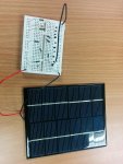
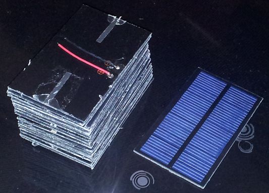
One obvious choice would be to use a solar panel and rechargeable batteries. I have committed the usual “click before you spec” sin and I am now the proud owner of a small solar panel, which may not be suitable, but I could buy a different one it necessary.

There is a lot of information on the forum and I was able to gain awareness of issues to consider, but I would like some guidance on how to put it all together. My question is about what the main building blocks of this system would be.

My thinking is outlined below:

The payload:

• Picaxe + ESP8266 + DS18B20
• Transmitting every 30 minutes for a minute (wake up, connect, transmit, go to sleep)
• Current usage when transmitting ~200-250 mA

Energy sources:

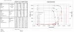
1) Solar panel, from China, nominal specs below:

• Operating voltage: 6V
• Working current 0.33A
• Open circuit voltage 7.2V
• Short circuit voltage: 0.38A

2) Single 3.2VLiFePO4 battery (AA size, they have about 700 mAh capacity)

I did some calculations on the energy needs and the suitability of the panel

• Average current = 6.5 mA (200 mA for a minute every 30 minutes)
• Daily usage: 6.5 * 24 = 156 mAh
• Weekly usage: 156 * 7 = 1092 mAh
• Charging efficiency (circuitry + chemistry) = 10% (assumed)
• Weekly solar panel charge requirement: 10920 mAh
• Daily charging hours (average) = 10920 / 0.33 / 7 = 4.7 --> need a bigger panel?

My questions are:

1) Do I need a bigger panel?
2) Is a single LiFePO4 cell enough to power the payload?
3) I presume I need a board to manage the charging. Would this one be suitable?

http://www.ebay.co.uk/itm/181728713087?_trksid=p2055119.m1438.l2649&ssPageName=STRK%3AMEBIDX%3AIT

I also saw this website www.talkingelectronics.com but, for the price, the board above is hard to beat

4) Do I need to control the charger with the Picaxe or can I let the charger board do it “unsupervised”?
5) Can I power the Picaxe with the battery while charging? Will I need a voltage regulator downstream of the battery (hopefully not)?
6) Will I need to implement a battery discharge protection?
7) What other issues should I consider?

It is a long list of questions, I know, but hopefully the answers it will not be useful to me. Also, happy to read other threads if this has been discussed before.

Many Thanks
Riccardo
 
Last edited:

srnet

Senior Member
For the UK plan for around 25% of the stated output of the panel during 8 hours of daylight.
 

hippy

Technical Support
Staff member
I am no expert in LiFePO4 technology but I believe they need some care in their charging and discharging regimes. I don't have any recommendations nor the experience or expertise to comment on any solutions.

It would almost certainly not be considered acceptable to simply connect up a solar panel and hope they charge safely.

You will probably also need something which ensures the battery does not discharge further than some voltage.

It's therefore likely to need some sort of battery management system for both charging, and handling discharging / use.
 

rmeldo

Senior Member
For the UK plan for around 25% of the stated output of the panel during 8 hours of daylight.
So, since the panel stated current is 0.33 A, should I plan for ~80mA for 8 hours, i.e. 640mAh/day ? How much of this will be stored in the battery (I assumed 10%, but was I too conservative?)?

Thanks
Riccardo

Thanks
Riccardo
 

AllyCat

Senior Member
Hi,

You presumably want it to work reliably in the Winter-time? IMHO both the panel and battery are too small.

PV panels are rated at 1000W/m2, which you'll never see in the UK (maybe 800W/m2 at mid-summer noon) and in winter it's about 400W/m2 if pointed directly at unobscured midday sun. The solar intensity is a half-sinusoid, so for winter assume 4 hours per day if there is a clear sky. So the "300mA" panel is perhaps good for an average 20 mA over a bright winter's day. That is needed not just to power your electronics but to recharge the battery for the (many) days which didn't have bright sun.

The battery size will be determined by how many "grey" days (with little or no charging) that you can tolerate, but it may be worth considering a SLA to get you over the whole mid-winter period when the light level is low (or perhaps effectively non-existent).

LFePO4s are commonly used in the better solar lights because they are well matched to the task. They tolerate moderate over-charging (bearing in mind that the peak solar energy is quite well-defined) and white LEDs draw negligible current below 3 volts so excessive discharge is largely avoided. But a 6 volt panel is not well matched to a 3.2 volt cell so you should use at least a PWM "buck" voltage converter and perahps a proper "intelligent" controller. Also, if the battery voltage is getting low, then reduce the frequency or period of data transmissions. As for efficiency, the PV panel itself should be between 8 and 16% depending on type, but a well-designed charge-discharge system might be good to around 75%.

The charging board you linked is for an 18650 cell which is significantly larger than an AA (14500) cell and probably the absolute minimum size that you should be considering.

Cheers, Alan.
 
Last edited:

rmeldo

Senior Member
Hi,

Thanks for the feedback. This is very useful. I went back to other threads and web pages I had read before and understood much more.

I also measured the panel: it is 0.124 m^2, so using a 1000W/m^2 and the spec I calculate an efficiency of 14.5% (optimistic?).
So at 400W/m^2 and using 10% efficiency (I presume efficiency is reduced in low light) I am left with 0.5W. Also I presume the voltage will be lower than the battery voltage, so perhaps I need to use a larger and higher voltage panel (reading your post you might have hinted this)? What would you recommend, 9V, 12V or else?

I also get the point about the battery size and I can do the power management by reducing the frequency of the transmission events until I learn to reduce the energy used for a single transmission event (I can store the intermediate readings and send everything in one go, say, every 4 hours).

With regards to the charger, would this one below be more appropriate than the link I posted previously (good efficiency, adjustable current and voltage)?

http://www.ebay.co.uk/itm/5A-DC-Buck-Converter-Constant-Current-12v-24v-car-Solar-Battery-Charger-w-PWM-/400738160975

In other threads people mentioned several times that the PV panel is naturally current limited. The value 5C has been quoted. Does this mean that if I select the solar panel according to this then I need ot set the voltage limiter in the buck converter circuit to a higher level than the PV panel and only use the converter for voltage limiting?


Many Thanks
Riccardo
 

manuka

Senior Member
Downunder corner (where high UV levels & super clear skies make even 1000W/m^2 quite tame).

I've been using diverse LiFePO4 cells & batteries for ~3 years, & have become a great fan of their near bullet proof tolerance & reliability. There's not much I can add to the above sharp answers, except to say 3.2V LiFePO4 cells should be ideally CC charged to 3.6V & not run dead flat. Skinflint charging & monitoring setups may however have merit - check my Instructable from 2013.

An appealing approach may be to simply use an off the shelf LiFePO4 power solar lamp as an "engine". These increasingly abound in the UK 10 pound range, & (if their near dazzling light output is any guide) should be quite up to a simple wireless task.

Surely however the hardware setups/converters in this application tend an overkill for just(?) wireless temperature data ? What sort of WiFi range is intended anyway? You may well get by with lower TX power & a simple directional antenna! At 2.4GHz these are simple,compact & high gain. Stan. in sunny NZ
 

BeanieBots

Moderator
I don't think I can add any more on the topics covered by AllyCat except to say I'd be even more conservative on panel size.
As for the battery, I would opt for NiMh rather than LiFePO4. They can be charged at C/10 indefinitely. Size needs to cover you for at least two weeks in UK winter. I would also try to get the panel volts closely matched for maximum power direct into the battery without the need for any converter. At low power, converters tend to use more power than they give back by increased efficiency.
Manuka brings up a good point about your power requirement. Whilst you have done a great job of understanding the power requirements of what you have, the power requirement for what you are trying to do is way over the top. My (purchased) wireless thermometer has it's 2*AA dry cell batteries changed every eighteen months. I've often thought of adding a solar panel but so far can't be bothered. A rechargeable cell will need replacing every couple of years anyway.
Maybe consider the cheap low power units to send the data back to a mains powered base station containing the ESP8266 as a way of reducing the remote power requirement.
 

AllyCat

Senior Member
Hi,

I calculate an efficiency of 14.5% (optimistic?).
...... (I presume efficiency is reduced in low light)
....... Also I presume the voltage will be lower than the battery voltage, so perhaps I need to use a larger and higher voltage panel

..... would this one below be more appropriate than the link I posted previously (good efficiency, adjustable current and voltage)?
IMHO, the answers to most (or all) of those items is NO.

There is no reason why the efficiency should reduce, but certainly the output power will. It's often not appreciated how much lower the light level (and thus PV power) is in "dull" conditions, typically only 10% and maybe just 1% of direct sunlight.

PV panels are fundamentally constant voltage until reaching the (highly variable) point where the current is limited by the available light (energy) input. Note that both the specification points (open-circuit voltage and short-circuit current) deliver NO power, so the (very difficult) "trick" is to find the point where as much current as possible is taken before the voltage starts to fall significantly. That's what your ebay link in #1 attempts to do (but I've no idea how well).

You might need a diode (there may be one already inside the PV panel) to prevent current flowing back from the battery. In practice, probably no regulator, or a simple linear regulator for 3.6 volts (LiFePO4) or 4.5 volts (3 x NiMH) if you want to be "kind" to the cells, may be good enoungh and "guarantees" to give you better than 50% efficiency into the cells at reasonable light levels. dc-dc converters give their best efficiency close to their maximum rated output power, so the latter "5 Amp" one you've linked might give terrible efficiency at 100 mA or below.

Finally, to reiterate what others have said above; it's probably better to pay attention to reducing the power budget (load) rather than changing the solar panel. But, we really need to know why you've assumed 1 minute transmissions over WiFi, rather than more conventional (and efficient) <1 second bursts at 434 MHz.

Cheers, Alan.
 

Hemi345

Senior Member
I think your 1 minute time to transmit the data using the ESP8266 is too long. In one of my projects, I have the ESP8266 switched on it's own 3.3V LDO. The PICAXE powers up the ESP8266 via the LDO enable pin, connects to my WiFi AP, transmits the data, and then powers it back down all in about 10-15 seconds total. Current while everything is sleeping in between transmits is around 14uA.

I concur with BeanieBots on using NiMH. I have a device that has been charging NiMH using nothing more than a ~280mA rated panel separated by a diode and using an n-channel mosfet to short the solar panel to ground when charging isn't needed. It's been running great for over 3 years on the same set of Eneloop AA batteries. I'm sure a more efficient method could be used by utilizing an MPPT IC but I'm happy with the design I'm using.
 

rmeldo

Senior Member
Thank you all for all the advice.
The ESP is really power hungry, I know, but I want to do a solar charging project so, since I have just built the ESP base temperature sensor to go with the gas consumption datalogger, I thought I would merge the two and build WiFi thermometer.
The two go well together so that gas consumption can be compared to the heating needs and perhaps in time I could build a heating controller….
I think I get now the fact that I need a larger, lower voltage panel. For the time being, and since the hardware is cheap, I will go ahead and buy the charger and a battery, start experimenting and see how it goes. After all isn't one definition of a hobby “an activity where you waste a large amount time, cash and energy just for the sake of it”?
I also found this: http://www.aliexpress.com/item/5pcs-5V-Micro-USB-1A-18650-Lithium-Battery-Charging-Board-Charger-Module-Worldwide-Store/32248718072.html?spm=2114.01020208.8.5.75gTNr.
It is a 4.2V device, but I thought that if I fitted a diode in series to avoid reverse current it would be fine (it doesn’t have a reverse current protection). Any thoughts?
Going back to the ESP8266, one minute of “on time” is a rounded figure, but 40-50 seconds is more typical. The time is spent waking up the device, connecting it to the SSID, to the web server and then transmitting. I control the ESP8266 through AT serial commands. I have seen people quoting ways to reduce the on time, the two main ones being to listen for the OK response to commands, rather than relying on fixed wait time and assigning a fixed IP address to the ESP. The big one also is to go native and program the ESP to run on its own rather than being driven by a Picaxe this can get the on-time down to about 10s. I have tackled none of these yet as I want to get the temperature sensor out for the winter.
In reply to the comments on whether a 433MHz transmitter to a receiver board with ESP on board and powered by a mains power supply, I agree strictly speaking it makes very good sense for the application due to the low power demand.
Thanks again
Riccardo
 

rmeldo

Senior Member
Hi Hemi345,


I think your 1 minute time to transmit the data using the ESP8266 is too long. In one of my projects, I have the ESP8266 switched on it's own 3.3V LDO. The PICAXE powers up the ESP8266 via the LDO enable pin, connects to my WiFi AP, transmits the data, and then powers it back down all in about 10-15 seconds total. Current while everything is sleeping in between transmits is around 14uA.
Yes, I think my non optimal code is a big factor in the transmission time. I saw the code you posted recently in another thread on the ESP8266. I was going to use it but I ran out of programming space and so I used just fixed delays. Perhaps I was too generous there. In my project the LDO is on all the time, but I don't draw any current. Instead I use the Picaxe to set the ESP8266 enable pin high.

In this thermometer I will have more programming space, since I am not using a RTC, no EEPROM and no LCD, so I should be able to use your code. Are there any other tricks I should be aware of? Better code?

I concur with BeanieBots on using NiMH. I have a device that has been charging NiMH using nothing more than a ~280mA rated panel separated by a diode and using an n-channel mosfet to short the solar panel to ground when charging isn't needed. It's been running great for over 3 years on the same set of Eneloop AA batteries. I'm sure a more efficient method could be used by utilizing an MPPT IC but I'm happy with the design I'm using.
And when I thought I had way forward on the battery side... here it comes this curve ball!

This sounds quite good, So I would need three batteries in series and cut the charging when reaching 3.6V (the ESP8266 works in the range 2.5 -3.6V), then cut the discharging when reaching 3.3V. This range would be good for the Picaxe too, so that I can do away with LDOs. Makes sense?

Many Thanks
Riccardo
 

BeanieBots

Moderator
Hi rmeldo,
Here's some real solar data for you so that you calculate your panel requirements.
I live about 2miles north and 1 mile east from where you work. On top of the hill.
My house faces 10 degree east off due south, so almost as good as it gets for solar.
I have a 2.5kW solar array on a standard pitch roof.

On a good sunny summer day, I can harvest up to 18kWhrs. None that high this year.
Best harvest for Sept-15 = 14.22kWhrs
Worst harvest for Sept-15 = 3.44kWhrs
Over the last week:-
14th 8.92kWhrs
15th 1.53
16th 0.69
17th 3.88
18th 4.61
19th 4.64
20th 7.86 It was a lovely sunny day all day!

In the run up to Xmas, I will expect about a dozen days where it will be < 0.1kWhrs.
This is all part of the joy of living in the UK.

The 2.5kW array is mono-crystalline.
I also have a 60W amorphous array (about 15 years old now). It fairs much better than the mono-crystalline on overcast days but cannot compete in full sun.

For the battery, yes, I would suggest 3 NiMh cells.
Stop drawing if less then 3.4v but no need to stop charging as long your panel cannot give more than C/10.
 

Flenser

Senior Member
and using an n-channel mosfet to short the solar panel to ground when charging isn't needed
Hemi345,
A innovative approach. How do you decide "when charging isn't needed" for your NiMH batteries?
 

rmeldo

Senior Member
Thanks BB,

I remember you from my pre-kids days. Very glad to hear from you. I've come back to electronics after a long pause and this forum is still as great as I remembered it.

My setup would see less sun then ideal due to the positioning of the panel.

From all the advice received I have decided to split the project in two parts.

1) The first leg would be to build the thermometer with both the ESP8266 and a low power RF transmitter and experiment with transmission (and especially receiving, in the case of the 434 MHz RF), power consumption and LIFEPO4 batteries. This will allow me to quickly start logging temperature data. I will have to periodically go outside and change the batteries

2) The second would be to build a solar panel + batteries + load prototype and experiment with charging. I think I need to do this, because I do not have enough knowledge of solar charging and I would likely end up with a wrongly sized charger, an unsuitable location and long delay in deploying the thermometer. EDIT: Very difficult to do this project at night

Thanks
everyone for the advice
Riccardo
 
Last edited:

hippy

Technical Support
Staff member
From all the advice received I have decided to split the project in two parts.
That's definitely a good strategy. Get what you want working even if that is sub-optimal. You can tweak things to make it better while having it at least usable and useful. You may even find it isn't that bad and may even be acceptable as it is.

Having something working, even if a prototype, is a good motivator to pushing on with a project. It helps show where issues are and real world results will also be useful in determining power and charging requirements.
 

grim_reaper

Senior Member
I have seen people quoting ways to reduce the on time, the two main ones being to listen for the OK response to commands, rather than relying on fixed wait time and assigning a fixed IP address to the ESP.
I would definitely recommend a fixed IP network for anything that's not a 'browsing computer'. Just allocate half your network addresses to you routers/modems/switches/servers/PICAXE interfaces as fixed addresses, and change the DHCP on your internet connection device to allocate only the other half to laptops/visitors/phones/etc.
(I know nothing about ESP, [the device, not ghost hunting] but I think I'd also want to persuade you to listen for OK responses too.

Looking forward to seeing some diagrams and photos of your finished solar system!
 

Hemi345

Senior Member
Hemi345,
A innovative approach. How do you decide "when charging isn't needed" for your NiMH batteries?
When the battery voltage (four AA), as read with calibadc10, reaches 5.1V. Real battery voltage is 5.3V because of the diode between the batteries and PICAXE. It enables charging when battery drops to 4.6V
 

Hemi345

Senior Member
I would definitely recommend a fixed IP network for anything that's not a 'browsing computer'. Just allocate half your network addresses to you routers/modems/switches/servers/PICAXE interfaces as fixed addresses, and change the DHCP on your internet connection device to allocate only the other half to laptops/visitors/phones/etc.
(I know nothing about ESP, [the device, not ghost hunting] but I think I'd also want to persuade you to listen for OK responses too.

Looking forward to seeing some diagrams and photos of your finished solar system!
I'm using the AT command firmware and 8 months ago when I was working with the ESP8266, there wasn't anything available to set a static IP (tried a few different firmware and ultimately went back to the AiThinker version that came on it at the time). That might have changed by now. But I ended up just using a DHCP reservation and punching in the ESP8266's MAC address. That shaved a couple seconds off the connection time.

Ditto on seeing the 'finished' project (they're never finished :) )
 

rmeldo

Senior Member
Some Data

I took some electrical measurements from the solar panel. I thought they would be useful for others too.

I used a home made "multiplexer" (see photo) and I took measurements with 1)artificial light, 2)daylight this morning at 8am (very overcast) and 3) daylight during the lunch break (still overcast).

The data is attached, together with a chart with current in logarithmic scale and multiplexer.

It doesn't look too bad. The only thing is that the panel voltage is too high. for a single battery. Salvageable though? I have some LDOs which I could use.


Riccardo
 

Attachments

Last edited:

Haku

Senior Member
I'm following this thread with interest because a few days ago I received a little stack of twenty 60x140mm 5.5v 150ma rated solar cells to tinker with:


Haven't had a chance to properly test them in full sunlight for obvious British weather reasons this time of year, but my initial intention is to see if I can make a portable folding USB charger using 10 of them, to charge up a USB battery pack rather than directly charge a phone/tablet etc.
 

Flenser

Senior Member
The only thing is that the panel voltage is too high
rmeldo,

You may find that your panel is OK. Solar panels are nearly constant current devices, at least close enough to constant current for our purposes. You can see this in your data where the current is nearly vertical (i.e. constant) through the resistor values 30, 58 and 298 ohms and not far off the vertical for 1290 ohms.

The internal resistance of the battery varies depending upon how fully charged it is. When it is not fully charged a battery has a low internal resistance and so on the 23/10/15 overcast day at home if you had connected the solar cell directly to the battery then the voltage across the solar cell would have been "pulled down" to the voltage across the charging battery.

I'll try and make my point clearer with a hypothetical example. You were getting about 2mA on the 23/10/15 overcast day at home, which is pretty low for charging any 18650 LiFePO4 battery. If, for example, the LiFePO4 battery voltage when being charged with 2mA was 3.1V then based on your data I predict that your solar cell you have would have perfectly happly supplied ~2mA @ 3.1V when connected to my example battery. The same applies to the other two days. Under the artificial light the solar cell would have supplied ~7mA @ 3.1V and on the overcase day at work it would have supplied ~35mA @ 3.1v.

When you come to the point where you choose how you are going to charge the battery with a solar cell you effectively need to provide the correct care when charging.
- If the charging voltage is allowed get too high it can damage the battery.
- If the discharging voltage is allowed to get to low it can damage the battery.
- If the charging current is too high it can damage the battery. (If the solar cell is small enough then it can only provide a small current and this may not be a problem)
- If the battery is charged for too long it can damage some batteries. (May not be an issue for solar chargers)

If you end up using a charging chip then that chip takes care of most of this for you, with the possible exception of preventing the voltage from being discharged to too low a value.
If you don't use a charging chip then you will need to consider how you are going to do the same thing yourself. In post #10 Hemi345 describes how he uses an n-channel mosfet to short the solar panel to ground when charging isn't needed. In post #18 he expands on this to explain how he monitors the battery voltage using calibadc, stops the charging once the battery voltage gets to 5.1v and enables it again once the voltage drops to 4.6V.
 

rmeldo

Senior Member
Thanks for the explanation.

I have ordered this, which got the thumb up from the forum:

http://www.ebay.co.uk/itm/181728713087?_trksid=p2055119.m1438.l2649&ssPageName=STRK%3AMEBIDX%3AIT

And some lifepo4 batteries.

When they arrive I will be able to experiment.

I think I could also implement the hemi345 control (post #10,18) on top, if necessary.

I also think I get the point that other people have made about matching the panel specs to the batteries and load: if the max voltage delivered by a panel was 3.7v (in the case of a LiFePO4 battery and with the reverse current protection diode installed) then it would be possible to have a very simple and efficient system where the panel is connected directly to the battery and load and the only check would be that the Max charging current is not exceeded, in very sunny or very cold days. Is this right?

On the other hand, however, with a 3.7v panel it wouldn't be possible to fully charge the battery on overcast days. So perhaps this strategy would work best in sunny locations?

Talking about temperature, while the LiFEPO4 option seems perfect, as many others have pointed out, for projects that can operate with voltages in the range 3.0-3.7 V, (with 3 NiMH the charging would have to be stopped above 3.7 v and the discharging too), they cannot be charged below 0°C, and that forces to have large capacities than NiMH battery which do not have this limitation.

Interesting subject.

Many thanks
Riccardo
 

rmeldo

Senior Member
Quick question:
Is there a way, available at hobbyist level, to measure the intensity (W/m2) of the light hitting the solar panel?
Thanks
Riccardo
 

AllyCat

Senior Member
Hi,

... at hobbyist level, to measure the intensity (W/m2) of the light hitting the solar panel?
No I don't think so. You need a suitable and accurately calibrated "Pyranometer".

AFAIK, the "only" method for a hobbyist is to wait for a "clear" (blue sky) day and compare the PV panel output with the "expected" intensity (technically often called "insolation"). That of course varies throughout the day/year, but the data should be available on the web, or in meteorological software such as "Cumulus" (note that the "typical maximum" figure in its "solar" graphs is for a horizontal panel).

Also, the type of panel is quite important. Amorphous Silicon cells (e.g. the type fitted in cheap garden solar lights) are sensitive almost entirely to visible radiation (light), but Crystaline Silicon cells actually have their peak sensitivity in the (near) Infra-Red. Typically almost half of the available energy is Infra Red; that's one reason why Amorphous Silicon cells have an efficiency below 10%, whilst the best Crystalline cells can approach 20%.

The charge controller you've ordered is basically just a (precision) voltage regulator, it's not a MPP (Maximum Power Point) solar charge controller (which hardly seems necessary for this application). Note that it needs to be configured (no link) for 3.6 volts for LiFePO4, not the 4.2 volts for "normal" lithium cells. Typically, 3 NiMH cells would be charged to a maximum 4.4 volts and the "nominal" voltages of the three technologies are 3.2, 3.7 and 3.6 volts respectively.

Note that what you may really need is an "ultra low quiescent current" regulator; a typical voltage regulator may take the "first" ~3 mA of any input current (and a Switched-Mode type much more), which might be all that your PV panel is delivering on a dull day). :(

Cheers, Alan.
 

AllyCat

Senior Member
Hi,

Yes that's right. You might not find a specific 3.6v version, but most regulators (or the "adjustable" version of MCP1700) can give a higher output voltage by "sitting up" their "ground" pin. For example put a (forward) Schottky diode (~300mV) in series with the pin, or (as the ground/reference current is so low) a potential divider from the output pin to ground (say 22k + 2k2). But beware that the maximum 6 volts input (and power dissipation) might be a bit tight with your PV panel.


I took measurements with 1)artificial light, 2)daylight this morning at 8am (very overcast) and 3) daylight
What type of artificial light? There is an enormous difference between the types of lamp.

LED lamps emit no Infra Red and "Compact Fluoescent" not very much, but the old-fashioned incandescent (tungsten filiament) lamps emit an enormous amount of IR. For a similar subjective (visible) light level my (Crystaline) Silicon PV sensor (BPW34) detects about ten times more energy (watts/m2) from an incandescent lamp, compared to a CF or LED type.

Cheers, Alan.
 

beb101

Senior Member
Quick question:
Is there a way, available at hobbyist level, to measure the intensity (W/m2) of the light hitting the solar panel?
Thanks
Riccardo
I bought one of these a couple of years ago for $119.00 (lost the link). Amazon is selling them for $157,

http://www.amazon.com/General-Tools-Instruments-UV513AB-Digital/dp/B002JOR0JO

It is NIST traceable calibrated at 365 nm.

Here is a cheap UV index meter. It is one of the few that also displays mW/cm**2

http://www.amazon.com/Ultra-Violet-Light-Detection-Kit/dp/B001B54TFK/ref=pd_sim_469_4?ie=UTF8&dpID=312YMUBl5xL&dpSrc=sims&preST=_AC_UL160_SR160,160_&refRID=0HNM2CA283G184KBVZW7#customerReviews

This meter uses the ML8511 chip. Sparkfun has a breakout for $13,

https://www.sparkfun.com/products/12705
 

rmeldo

Senior Member
What type of artificial light? There is an enormous difference between the types of lamp
It was a fluorescent light. One of those desk lamps with a magnifying glass in the centre and a fluorescent ring tube.
 

Flenser

Senior Member
Is there a way, available at hobbyist level, to measure the intensity (W/m2) of the light hitting the solar panel?
For a hobbyist:
You could use other people's data. I could not find detailed figures with a quick google search, only daily averages.
From the met office: http://www.metoffice.gov.uk/renewables/solar
From a company selling solar panels: http://www.theecoexperts.co.uk/freebook/appendix-solar-insolation-values-uk
The second one has the nice feature that they include average values for the panel at several useful angles.

Instead of using real data you could use a model. Here is one example that ends up with a comparison between the model and actual pyranometer output: http://www.brighton-webs.co.uk/energy/solar_earth_sun.aspx

This person has a page on Diffuse Radiation experiments http://www.brighton-webs.co.uk/energy/diffuse_irradiance.aspx that suggests another way for a hobbyist to measure this data using a solar cell:
The short circuit current of the photocell is directly proportional to the irradiance, in this case the short circuit is provided by a 10 watt 1 ohm resistor, the voltage across indicates the current through the cell.
 
Last edited:
Top