OK, I finally got some time and am ready to connect my stepper motor assembly to the hardness tester.
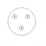
I was hoping to hook up to the start switch and the beeper in the unit. I really don’t want to tear into the machine if I don’t have to. There is one of two connectors in the back that may be a possibility. All it says is AT above one and is a 3 pin connector. Looks like the attached image. (There is another connector back there that says Parallel that looks like a half sized connector you would find on a printer but I know nothing about it)
Here are the voltages at the different states.
Machine just sitting there
Chassis is Ground:
Ground to Pin 1..+4.75 Volts
Ground to Pin 2.....0.00 Volts
Ground to Pin 3.....0.00 Volts
When you push the Start button:
.............................Just.................Push.................After
.............................Sitting..............Start................Cycle
.............................There...............Button.............Finished
Ground to Pin 1...+4.75 Volts......+4.75 Volts......+4.75 Volts
Ground to Pin 2.....0.00 Volts.........0.00 Volts........0.00 Volts
Ground to Pin 3.....0.00 Volts.......+4.75 Volts........0.00 Volts
When you push the Start button:
.......................Just...........Push........After
.......................Sitting........Start.......Cycle
.......+....-........There.........Button.....Finished
Pins 1 & 2......+4.75.......+4.75........+4.75
Pins 1 & 3......+4.75..........0.00.......+4.75
Pins 2 & 3.........0.00.......-4.75..........0.00
I want to get the Micrometer positioned, hit the start button on my circuit which moves the Micrometer to the first position, send signal to the tester then the tester does it’s thing which takes 15 to 20 seconds. Moves the Micrometer to the next position and so on. (Does all this make sense)
Any Ideas?
[FONT="]Mike[/FONT]
Attachments
-
 6.7 KB Views: 6