calvinsykes
Member
A first draft for a radio control, see what you think ")
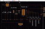
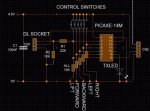
Transmitter:
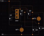
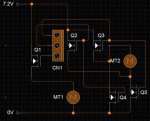
Receiver:
EDIT: Knew I had the commented version lying around somewhere.
This is for a hovercraft where I have a servo for steering and three FETs for control of the thrust and lift motors. At present using a load of switches at TX end but investigating something like this:
http://www.sparkfun.com/products/9032
Transmitter:
Code:
init:  'set up symbols so i can remember what means what
    symbol servo_pending = b1 'variables i'll use later, just giving them nicer names
    symbol thrust_pending = b2 'they keep track of what commands I need to send
    symbol lift_last_sent = b3 '
    symbol lift_pending = b4 '
    symbol lift_wait_time = b5 ' timer to debounce lift toggle (more about that further on)
    symbol servo_left_pin = pin4 'pins for various switches
    symbol servo_right_pin = pin3'
    symbol thrust_fwd_pin = pin2'
    symbol thrust_bkwd_pin = pin1'
    symbol lift_pin = pin0'
    symbol txled_pin = 4 'pin number for flashy light
    symbol rftx_pin = 5 'pin number for outgoing serial data to rf transmitter
    symbol baudrate = T2400_4 'the speed of the serial connection, in bits per second

startup: high txled_pin 'just flash light to say "I've turned on!"
    pause 1000
    low txled_pin
    let lift_last_sent = "N"

checkpins: 'now we see if any buttons are being pressed
    if servo_left_pin = 1 then
        let servo_pending = "L" 'need to transmit "turn right"
    elseif servo_right_pin = 1 then
        let servo_pending = "R" 'need to transmit "turn left"
    else
        let servo_pending = "M" 'don't want to turn so transmit "go to middle"
    endif
    if thrust_fwd_pin = 1 then
        let thrust_pending = "F" 'need to transmit "go forwards"
    elseif thrust_bkwd_pin = 1 then
        let thrust_pending = "R" 'need to transmit "go backwards"
    else
        let thrust_pending = "O" 'don't want to move so transmit "turn off the thrust fan completely"
    endif
  'lift is a bit trickier; don't want to have to hold down the "hover" button all the time so we do this:
  if lift_pin = 1 and lift_last_sent = "I" and lift_wait_time > 20 then 'toggle pressed, fan is on atm
        let lift_pending = "O" 'so we want to transmit "turn it off"
        let lift_wait_time = 0
    elseif lift_pin = 1 and lift_last_sent = "O" and lift_wait_time > 20 then 'toggle pressed, fan is off atm
        let lift_pending = "I" 'so we want to transmit "turn on"
        let lift_wait_time = 0
    elseif lift_pin = 1 and lift_last_sent = "N" and lift_wait_time > 20 then 'toggle pressed, but its the first time it has been
        let lift_pending = "I" 'so we want to transmit "turn it on"
        let lift_wait_time = 0
    elseif lift_pin = 0 then 'toggle isn't on, so we want to transmit "stay in same state you are atm"
        let lift_pending = lift_last_sent
    endif
    let lift_wait_time = lift_wait_time + 1 'put in a counter so that if you hold down button, lift doesnt keep toggling on and off 10,000 times a second :O

transmit: 'now we send the requests
    high txled_pin 'flash light to show we are doing something
    serout 5, baudrate,  (0x55, 0x55, 0x55, 0x55, 0x55, 0x55, 0x55, 0x55) 'preamble of 01010101s to tune reciever
    pause 15
    serout 5, baudrate, ("data", servo_pending, thrust_pending, lift_pending) 'send the commands
    low txled_pin 'light off
    let lift_last_sent = lift_pending 'update lift state memory
    goto checkpins 'start again
Code:
init: 'more symbols
    symbol servo_state_pending = b0 'variables again; how I'll determine what needs doing, quickly
    symbol servo_state_current = b1'
    symbol servo_needs_changing = b2'
    symbol thrust_state_pending = b3'
    symbol thrust_state_current = b4'
    symbol thrust_needs_changing = b5'
    symbol lift_state_pending = b6'
    symbol lift_state_current = b7'
    symbol lift_needs_changing = b8'
    symbol servo_pin = 4  'pin number for servo
    symbol servo_middle_pos = 150 'rotation amounts for three servo positions
    symbol servo_left_pos = 160'
    symbol servo_right_pos = 140'
    symbol rfrx_pin = 0 'pin number for incoming serial data from rf receiver
    symbol baudrate = T2400_4 'rf link/serial data rate
    symbol fwd_pin = 0 'pin numbers for power transistors to switch motors on and off
    symbol bkwd_pin = 1'
    symbol lift_pin = 2'
    symbol rxled_pin = 3 'pin number for flashy light

startup: 'set some stuff up
    servo_state_current = "M" 'servo should be in middle...
    thrust_state_current = "O" '...thrust should be off...
    lift_state_current = "O" '...and so should lift
    high rxled_pin '"I've turned on!" again
    pause 1000
    low rxled_pin
    servo servo_pin, servo_middle_pos 'actually move servo incase someone has fiddled while it was off
    pause 75

listen: 'wait for transmission from other curcuit
    serin rfrx_pin, baudrate, ("data"), servo_state_pending,thrust_state_pending, lift_state_pending 'read requests from transmitter into these variables
    high rxled_pin 'show something is happening
    goto receive

receive: 'so what now?
    if servo_state_pending != servo_state_current then 'requested servo position different from current
        let servo_needs_changing = 1 'so we'll need to do something about it
        gosub srvo 'go and do it
    endif
    if thrust_state_pending != thrust_state_current then 'requested thrust different form current
        let thrust_needs_changing = 1 'so we'll need to do something about it
        gosub thrust 'go and do it
    endif
    if lift_state_pending != lift_state_current then 'requested liftdifferent from current
        let lift_needs_changing = 1 'so we'll need to do something about it
        gosub lift 'go and do it
    endif
    low rxled_pin 'receive done so turn light off...
    goto listen 'and do it again

srvo: 'move servo around
   if servo_state_pending = "L" then 'want to move to left
        servo servo_pin, servo_left_pos
        pause 100 'give servo a chance to move
    elseif servo_state_pending = "R" then
        servo servo_pin, servo_right_pos 'want to move to right
        pause 100 'give servo a chance to move
    elseif servo_state_pending = "M" then 'want to move to middle
        servo servo_pin, servo_middle_pos
        pause 100 'give servo a chance to move
    endif
    let servo_state_current = servo_state_pending 'update servo state memory
    return 'go back to where we came from

thrust: 'alter thrust fan configuration
      if thrust_state_pending = "F" then 'want to go forwards
        low bkwd_pin
        high fwd_pin
    elseif thrust_state_pending = "R" then 'want to go backwards
        low fwd_pin
        high bkwd_pin
    elseif thrust_state_pending = "O" then 'All stop, Cap'n
        low fwd_pin
        low bkwd_pin
    endif
    let thrust_state_current = thrust_state_pending 'update thrust state memory
    return 'go back to where we came from

lift: 'alter lift fan configuration
   if lift_state_pending = "I" then 'want to turn it on
        high lift_pin
    elseif lift_state_pending = "O" then 'want to turn it off
        low lift_pin
    endif
    let lift_state_current = lift_state_pending 'update lift state memory
return 'go back to where we came fromThis is for a hovercraft where I have a servo for steering and three FETs for control of the thrust and lift motors. At present using a load of switches at TX end but investigating something like this:
http://www.sparkfun.com/products/9032
Last edited: