PWM Problem.

Hello.

Iam very new with picaxe micro.

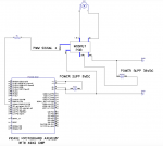
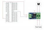
I try to make a pwm code for picaxe 40x2 with pcb mosfet and optocopler like
on the circuit attach.

When i test it the velocity of the motor not change.

Please seee the image here:
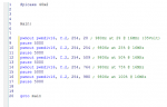
circuit01.jpg

The code here:
Code:
#picaxe 40x2

main:
pwmout C.2, 99, 99 ; 10000Hz at 25% @ 4MHz
pause 3000
pwmout C.2, 99, 199 ; 10000Hz at 50% @ 4MHz
pause 3000
pwmout C.2, 99, 299 ; 10000Hz at 75% @ 4MHz
pause 3000
pwmout C.2, 99, 399 ; 10000Hz at 100% @ 4MHz
pause 3000
goto main
I need put any type of resistor on the PWM pin?

Can someone help?

Thanks
Manuel
 

premelec

Senior Member
You need a common [V-] lead to the MOS board - it's not shown in your diagram - 3 wires at least required for two control pins - one is V- . However I don't know how the board is wired - perhaps there are more problems than this... it's safer to put a few hundred ohms R between PICAXE and MOS just in case something goes wrong... however it also depends on how the PCB MOS is wired... Looking again at the picture perhaps one of the PCB input pins should be V- ; or reversing voltage is supposed to reverse motor - can you give reference to the MOS PCB instructions?

On further thought - if this is just a unit with opto & CMOS likely it's a pretty slow turn on / turn off time and so unless your PWM is slow it won't register correctly [MOSFET gate is usually pretty large capacitor and needs a driver to turn on/of fast].
 
Last edited:

inglewoodpete

Senior Member
On further thought - if this is just a unit with opto & CMOS likely it's a pretty slow turn on / turn off time and so unless your PWM is slow it won't register correctly [MOSFET gate is usually pretty large capacitor and needs a driver to turn on/of fast].
I can confirm that 10kHz is too fast for a power MOSFET to switch at without using a really beefy gate driver. I suggest the following command for ~980Hz and 50% duty.
Code:
[color=Blue]pwmout pwmdiv16[/color][color=Black], [/color][color=Blue]C.2[/color][color=Black], [/color][color=Navy]127[/color][color=Black], [/color][color=Navy]255  [/color][color=Green]'50% duty[/color]
 
in fact negative picaxe signal and the negative power are not the same refrence! I will assemble the circuit and make the same reference and put a resistance for protection.
I will also modify the PWM values.

This small pcb is based on:

MOSFET IRF5305S/L
PHOTOTRANSISTOR JC817

Datasheets:
http://www.irf.com/product-info/datasheets/data/irf5305s.pdf
https://www.addicore.com/v/vspfiles/downloadables/Product Downloadables/optocoupler_JC817/Optocoupler JC817 Datasheet.pdf


Features:
FET module, input and output totally isolated from each other.
Signal trigger: digital high/low signal, can be connected to IO of micro-controller, PLC interface, DC power supply, etc.
The output can control high-power devices: motor, light bulb, LED light & strips, DC motor, small pumps, solenoid valve.
Input signal voltage: 3V~20V; Input current: about 5mA.
Output voltage: 5V~36V(Current: within 5A, Max. current is 20A. When current is over 5A, please add heat sink).

Specifications:
Input Signal: Voltage: 3V~20V; Current: 5mA
Output: Voltage: 5V~36V; Current: within 5A
Item Size: 46 * 25 * 18mm / 1.8 * 0.98 * 0.7in
Item Weight: 14g / 0.49oz
Package Size: 10 * 5.8 * 1.8cm / 3.94 * 2.3 * 0.7in
Package Weight: 15g / 0.55oz


When I finish I report as it was.
 

inglewoodpete

Senior Member
Does the MOSFET get hot after the motor has been running for 30 seconds? If it does get hot, that indicates that the MOSFET is not turning on fully.
 

premelec

Senior Member
Just for visual test of PWM signal put an LED in series with 1k R on 'AXE PWM output to see if it changes with PWM to confirm your PWM signal...
 

inglewoodpete

Senior Member
Specifications:
Input Signal: Voltage: 3V~20V; Current: 5mA
Output: Voltage: 5V~36V; Current: within 5A
  1. For a test, I suggest you connect the input wires to the 0v and +5v supply that you are using for the PICAXE. With the motor connected to the MOSFET board and running, measure the voltage across the MOSFET board (0v supply to 'low' side of the motor).
  2. Current flowing through the motor.
If the voltage measured across the MOSFET board is more then 0.5v, carefully measure the voltage across the Source and Drain of the MOSFET.
 

premelec

Senior Member
Yes that's good - just checking as you said it just kept running - perhaps try a PULSOUT signal or looping on/off and see if you can get control you want. It may just be PWM is too high frequency for the unit...
 

inglewoodpete

Senior Member
Yes that's good - just checking as you said it just kept running - perhaps try a PULSOUT signal or looping on/off and see if you can get control you want. It may just be PWM is too high frequency for the unit...
Why not turn it on fully and do some diagnostics as I suggested in post #11? It's best to avoid pulsing the input until it is proven that the MOSFET turns on properly.
 

premelec

Senior Member
Hi IP - he said FET didn't get hot and does turn on/off - what you suggested seems good... whatever works to check out basic functions... Maybe he hasn't got a DVM...
 
I try with PULSOUT, and i have some good results after burn some FETS. I need more time to study! When i have real values i come back here and post.
Thanks for all.
 
Top