Pump timer

marzan

Senior Member
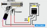
I have a 12 volt pump to ump rainwater ant near mains pressure. Fortunately for me I purchase 2 of them as I have an issue. There is a microswitch that detects the pressure and cuts out the pump. When the irrigation system is being supplied with rainwater the pump cannot remain on and so switches on and off very quickly. To fis this i have tried to add a water pressure tank. but the same thing happens. My theory is to set the pressure microswitch to a little less pressure and to build a timer circuit to leave the pump on for a pre-determined time once the first cut out is detected I have come up with this circuit using an 08M :
Pump timer.jpg

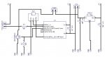
Have I missed anything out? If the amps of the motor are greater than the MOSFET, could I use 2 of them as I have a few of them, or would I be better using a relay?

Thanks.

Marz.
 

Colinpc

New Member
What is the head? (How high are you trying to pump the water?) It sounds to me that the weight of the water is sufficient to give the cutoff pressure.

Or, how much flow? If the flow is too low, the pump will chatter.

I use a pressure pump and accumulator tank in my caravan and have no problem with chattering. It switches on and off but does not chatter.

Yeah I know you want to use a Picaxe, but why if not needed?

Freddagg
 
Last edited:

SAborn

Senior Member
The simplest way would be to run a bleed line (bypass) back to the tank and adjust the bleed to stop the pump cycling, and more than likely use less power with not stopping and starting the pump.

A pressure tank will only work if it has a bladder inside with air pressure in it (normally about 30psi), as water will not compress and the air bladder is required to allow the air to compress giving a differential pressure.

There is pumps or controllers that will back off the pump to balance flow output without the need for a pressure tank.
 

marzan

Senior Member
What is the head? (How high are you trying to pump the water?) It sounds to me that the weight of the water is sufficient to give the cutoff pressure.

Or, how much flow? If the flow is too low, the pump will chatter.

I use a pressure pump and accumulator tank in my caravan and have no problem with chattering. It switches on and off but does not chatter.

Yeah I know you want to use a Picaxe, but why if not needed?

Freddagg
Only pumping 3 feet high, but because it is feeding a dripper system it cant run at full volume so the constant cutting in and out.
 

marzan

Senior Member
The simplest way would be to run a bleed line (bypass) back to the tank and adjust the bleed to stop the pump cycling, and more than likely use less power with not stopping and starting the pump.

A pressure tank will only work if it has a bladder inside with air pressure in it (normally about 30psi), as water will not compress and the air bladder is required to allow the air to compress giving a differential pressure.

There is pumps or controllers that will back off the pump to balance flow output without the need for a pressure tank.
The pressure tank I have borrowed is about 18 litres, and monitoring the air pressure in the tank I was able to play around with the pressure switch set to a lower level to still get quite good pressure. I want to get a 50 litre tank now so the pump can store a fair bit of water at good pressure. The pump is capable of 40 PSI but I will set the switch to 30 and set the picaxe to run on for a predetermined time after it detects the first trip of the microswitch. I can play around with the time to determine how long it needs to continue to run after the pressure switch has been tripped.I do realise that if water is being drawn off that the time will not be right,but my main concern is what the short tripping cycle of the micro is doing to the switch(getting hot) and the pump. Why the PICAXE? Because I have a heap of them that I got for a good price ;) (Thanks Pete)
Marz
 
Last edited by a moderator:

Colinpc

New Member
It appears to me that you are using the pump in a manner that it was not designed for. 12v pressure pumps such as Shurflo etc, are for running with a good flowrate, or, for short burst with low flowrate. EG, large flow rate of a shower and low flow for rinsing your toothbrush.

With a low flow, the switch pressure is achieved quickly and the pump stops. As the water flows, it starts again. This will cause the pump to chatter. With an accumulator fitted (mine is only about a litre) the pump does not operate with simply a quick rinse of your toothbrush but will when washing hands.

With a drip system, the flow would be low so the pump would chatter. With a large accumulator tank, I would expect the pump to run to pressurise the tank then stop until the pressure drops again. The time would depend on the flow.

What time do you have between cycles?

Maybe you could look at PWM to pump at the rate required without the need to cycle? After all, cycling is PWM at very low speed!

Freddagg
 

SAborn

Senior Member
I had missed the fact it was a 12v pump and yes PWM would be a good option.

As for stacking a few mosfets in parallel yes you can, and i would advise you do to keep the heat down, as they are a smd chip you will have trouble adding a large heatsink so best spread the load over a few chips.

The other problem i see is R1 should be to Gnd as a pulldown resistor or the input will float when the switch is open.
 

John West

Senior Member
Be sure to mount the paralleled MOSFET's side by side on a heatsink. They work best when working at the same temperature.
 

darb1972

Senior Member
Something minor, but I think that MOSFET is up the wrong way. If I am not mistaken, the internal zener/snubber should be the other way around for this driving configuration.
 

marzan

Senior Member
Something minor, but I think that MOSFET is up the wrong way. If I am not mistaken, the internal zener/snubber should be the other way around for this driving configuration.
The source is connected to the load is it not? Or have I got it wrong as usual :)
Marz.
 

sedeap

Senior Member
Drip irrigation best practices manual say... always use one large water reservoir (upland pond or tank) to keep pressure, so... if you have enough room or free space, use a tall "water column" to avoid pump chatter.
No need a fancy pressurized tank.... just a 3 meters 4" PVC pipe tied vertical to a tree, post or wall-side, do the job, that's used as reservoir, and you fill it to top, and let it drip away slowly...
Just put at top end a hole cap covered with mosquito net to avoid insects and leaves.
 

AllyCat

Senior Member
Hi,

The source is connected to the load is it not?
No, for an N-channel MOSFET the Source should be connected to, or towards, (negative) Ground. The way to remember/check is that the diodes shown in the symbol must NOT conduct current (unlike the base-emitter of a bipolar transistor) because they would just act as a "short circuit". So the "arrows" should point AWAY from the negative Ground.

Cheers, Alan.
 

SAborn

Senior Member
We dont really know the dripper system in use, so its a bit hard to suggest a header tank system, as here we have pressure compensated drippers and non compensated drippers, then there is in line dripper systems, octamitters and various other systems, all designed and installed to operate on a mains water pressure of 60-80 PSI on average.
so 3m of head would give 8.34 x 0.052 x 12 = 5.2 PSI to the drippers, not quite what the system might have been designed for originally.
 

marzan

Senior Member
Aaarrgghhh!! This " electrickery" stuff does my head in sometimes..
So , does that mean the big tab on the bottom of the package which I thought would be attached to the ground plane to act as a heat sink is actually on the positive side? So I would have to leave some copper around it to dissipate some of the heat? . BTW I did think of an easier way to do it by modifying the housing to take 2 microswithes for a low/ high latched relay circuit. But that might be something to manufacture when I get the 3d printer working.
 

rq3

Senior Member
Aaarrgghhh!! This " electrickery" stuff does my head in sometimes..
So , does that mean the big tab on the bottom of the package which I thought would be attached to the ground plane to act as a heat sink is actually on the positive side? So I would have to leave some copper around it to dissipate some of the heat? . BTW I did think of an easier way to do it by modifying the housing to take 2 microswithes for a low/ high latched relay circuit. But that might be something to manufacture when I get the 3d printer working.
Yes indeed. The tab will be "hot", both thermally and electrically. It should be soldered to as much copper area as possible. The source pin goes to common ground. You may also want to think about putting a 10K pull-down resistor on the microswitch input pin and change the existing 10K series current limit to 1K. As it is now, the pin is floating until the microswitch is actuated. And double check those 100 uF voltage regulator caps. Some regulators are very picky about the value of their decoupling. One final comment: don't forget the 22K and 10K programming pin resistors!
 

rq3

Senior Member
One final thought. The MOSFET you have chosen is not a logic level device. It probably won't turn on completely if driven by a Picaxe.
 

papaof2

Senior Member
We dont really know the dripper system in use, so its a bit hard to suggest a header tank system, as here we have pressure compensated drippers and non compensated drippers, then there is in line dripper systems, octamitters and various other systems, all designed and installed to operate on a mains water pressure of 60-80 PSI on average.
so 3m of head would give 8.34 x 0.052 x 12 = 5.2 PSI to the drippers, not quite what the system might have been designed for originally.
There are drip emitters designed for the low pressure provided by a standing column of water. I found a source in California that has emitters that work in the low single digit PSI range - as in a 55 gallon (~ 200 liter) barrel a foot (~0.3 m) or so off the ground.

I never went that route as even when outdoor water use was banned here because of drought, watering for food gardens was still permitted. My wife kept her flowers alive with collected rainwater delivered by a watering can (I have storage for more than 300 gallons)..
 

SAborn

Senior Member
The data sheet suggests about 1 sq/in of copper per chip for heat sink on a single layer board, for around 40C operation.
That makes a smd device a little bulky.
 

marzan

Senior Member
One final thought. The MOSFET you have chosen is not a logic level device. It probably won't turn on completely if driven by a Picaxe.
Would it work if it had another transistor to power them from 12 volt? I would imagine a PNP one? I`m not that crash hot on reading data sheets.
Marz.
 

marzan

Senior Member
The data sheet suggests about 1 sq/in of copper per chip for heat sink on a single layer board, for around 40C operation.
That makes a smd device a little bulky.
Yes you are right Pete. That`s a lot of space. But I guess I have a few of them and plenty of PCB, plus it sort of makes it easier to connect them to the power if it is to the tab. if the pump runs 15Amax and I use 2 MOSFETs rated at 12A would they still get as hot? Do they generate heat all the time they are on, or only when they are switching?
Marz.
 

SAborn

Senior Member
Would it work if it had another transistor to power them from 12 volt?
I tend to use a mosfet driver as they are easier than messing with transistors and do a much better job.
A common one for me is the TC4420, as they are avaliable local and not that costly. ( i have a few here in stock if you need)
One driver will control several mosfets, and as rule of thumb i tend to derate every mosfet by 50% to help keep the heat down.

http://pdf.datasheetcatalog.com/datasheet/microchip/21419b.pdf
 
Top