Project build

Steve_Reeves

New Member
Hi all,
I'm interested in building my first project build using the PICAXE EXPERIMENTER BOARD (AXE090), and would be intersted in suggestions on programing the 18X chip.
My intension is to use a piezo pressure transducer,input to the ADC,and output to a two digit LCD diplay.
The object of the exercise it to moniter boost pressure, to a turbo diesel engine, diplaying turbo boost pressure.
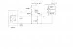
The Transducer is a automotive device with a 5v supply, ground, and signal out. The schematic drawing, i will post shortly.
Help would be much appecciated.
Regard's
Steve.
 

Mycroft2152

Senior Member
Hi Steve,

Welcome aboard!

Defintely post a schematic and links to datasheets of any unusual components that you are using.

You might also want to let us know what part of the world you are in. this will avoid some confusion when suggesting alternative suppliers.

Myc
 

Steve_Reeves

New Member
Hi myc, thank you for the welcome, I will forward the relevent info asap.
I preside in Maidstone, Kent. UK.
Regard's
Steve.
 

slimplynth

Senior Member
Hi Steve

Just an idea, not sure what the other forum members think but I'd have thought you'd get away with a 08M for this task. Just thinkin in terms of the amount of time soldering and cash by getting an AXE090. If all you need is an ADC input.

I got an AXE090 to start with, my soldering skills were not the best and it caused massive delays, nay upset:D getting started on the interesting stuff. That said I love my AXE090 birthday present, good sized bread board, LED indicators switches etc...

I posted a pdf of a simple 08M circuit constructed on perf board on the linked thread if it helps, it always works for me and requires very few components.

Regards

Elmo
 

manuka

Senior Member
Steve- is this a mobile diesel or stationary? I don't want to be a spoil sport, but Rev.Ed (the PICAXE makers) specifically warn against PICAXE automotive use, no doubt to cover themselves should a 1 in a million freak accident result.
 

Dippy

Moderator
Spoilsport! Seriously though, heed the advice re using PICAXE in a vehicle.

AXE090 is nice, I wish more people would spend the extra pennies and get one.

One thing that should also be asked is your level of electronics knowledge.
Automotive power supplies (i.e. the wires in your vehicle) can be noisy esp on old vehicles.
Newer ones tend to be better. The back of the cigarette lighter is a nice source and only has small rev-related pulses on it (a lot of engine diag machines take the rev signal from there).
Have you any exprience on noise and transient suppression on power supplies?
This can be crucial in vehicles. As is the use of fuses. And above all be neat and careful. Expensive/dangerous mistakes can be made.
That's the limit of my caveats... the rest is down to you. I'll leave the Gloom & Doom brigade to continue that theme.

People will be very helpful in giving advice on writing code but prefer to see you having a go first. If you want people to write the code for you then a lot of flattery is required :)
Don't forget to look in the manuals for initial advice and snippets. And searching on the Forum can produce some very helpful ideas.

As Myc says a Data Sheet on any unusual components is a must-do.
 

moxhamj

New Member
Just to anticipate those gloom and doom merchants, if you are just measuring something, automotive should be fine.

My 08 based fan controller for my car is now over a year old. I'm getting close to calling it more reliable than the system my car came with (the original died and then the engine got cooked). LM35 strapped to the radiator hose. 7805 reg (not a 78L05 as I wanted the robustness of the 7805). 22uF and 0.1uF across the power supply pins of the picaxe. Driving a BC547 via a 2k7 then to a small 1A relay (+back emf diode) which switches the existing relay for the fan. Shoehorned it all into a box near the battery. Metal box is the best for shielding etc. If I had wanted a display I would have gone for an 18X.

Pls post your schematic. There are lots of examples of measuring and display code in the 3 manuals in the help section.
 
Last edited:

Michael 2727

Senior Member
Many devices that run inside an automobile are just standard devices, but they
will have a lot of added/built-in design protection to avoid some of the strange things
that may occurr in a vehicle.

There are on the other hand devices specifically designed for Auto use.

Some of the unusual things that may/can happen are-
High Back EMF voltages from relays, solenoids and motors.
High Voltage spikes/noise fron ignitoin systems etc.
Power surges from dipping/engaging the headlights or other heavy loads.
Radical power fluctuations eg: starting the engine.
High voltages from static buildup.
General electrical noise/interference.
Temperature extremes.
And a bunch of other unforeseen things.

All of the above can disrupt, stop or worst case destroy a microcontroller.
( or other electronic devices )

A standard 3 pin regulator can only do so much, they don't do miracles though.
So if your design is a 7805 regulator in a plastic jiffy box you deserve everything you get.

I don't know of any Auto/Electronic design rules or tutorials, but I'm sure if you look
you will turn up something.
Many applications have been discussed previously on this forum and the design
parameters would be as diverse as the individual projects themselves.
Common Sense is a good tool to have handy.

Any micro should work sucessfully and without much trouble if good design
precautions are taken.
 

BeanieBots

Moderator
I can't see any diagrams!
All I can see is a table which doesn't say much.
It's a 5v (nom) device.
Output is a bit above 0v at min pressure and a bit below 5v at max pressure.
It's a fairly low impedance impedance output so it can be connected direct to ADC input. That's good. Is it linear?
Does the sensor spec match up with your manifold pressures? If not, you'll need scaling or worse, a different transducer.

What is your power supply?
Is this for use in a car?
How do you intend to drive the display? (4026?, charlieplex? other?).
 

BeanieBots

Moderator
OK, just seen your second post.
A bit of signal slugging and a modicum of supply decoupling. (1n5 Hmm...)
What's the 680k pullup for?
 

Dippy

Moderator
And what's Uh 5.5 to 16V for?

Red Herring: Can someone knock up and post a few ideas for protection of the PICAXE in vehicles please? The same old stuff gets posted so frequently there should be central resource for this sort of stuff. AND it could save a Newbie from an expensive mistake.
 

hax

New Member
Best protection in my opinion is a 12v mobile phone charger. They usually run at 4.7 to 5V output and they have an isolated switchmode power supply built in so that the phone they plug into doesnt go zap.

Of course, all the inputs and outputs should be optocoupled as well.
 

Michael 2727

Senior Member
Dippy, you looking to start WW111 ?

Looks like a standard MPX** or similar bridge transducer.
Dunno what the the "Uh" bizzo is, Supply 5V sounds good though.
You could probably do the whole thing on an 08M -inc display drive.

I listed some things that could go wrong - Post #8
For starters I'd suggest the unit be enclosed in a metal case & earthed to the car chassis.
All external wiring to the sensor should be shielded-heat resistant/waterproof/petrol-oil resistant optional, depends on placement etc.
Use plenty of large and small capacitors- see recent 7805 thread.
Over voltage zener clamping on picaxe inputs may help.
Resistors, pulldown to Neg on unused picaxe inputs.
FUSE, FUSE, FUSE the unit, did I mention use a FUSE !
Don't hack into any existing wiring, people behind you may find your brakelights useful.
And any other suggestions people may offer.
Did I mention, put a fuse on the thing ?

Good luck.
 

Dippy

Moderator
I know you did Michael. I saw it. And it's good advice and that's what prompted my suggestion.

I and many others (including you) have mentioned exactly the same stuff many times over the last x decades .. well it seems like that. And as it disappears into the temporal distance, far into the deep caves of Planet Archive, it would be so much nicer if a nice link to a fixed website page was available.

Even nicer would be an Appendix to a PICAXE manual "Getting Started" Appendix 3 "How PICAXE can survive in your (Dad's) car".
Followed by Appendix 4. "So, you didn't read it and connected your PICAXE to the ABS. LInk to Ebay funeral services".
 

BeanieBots

Moderator
SOMEWHERE in this forum is just such a link. I think it came up around the 47th post on PICAXE and cars. Can't find it now though. If anyone finds it, maybe we should make it a sticky.

Oh, nearly forgot. In case anyone read Michael's post too quickly, FUSES.

Here's a thread worth a revisit.
http://www.picaxeforum.co.uk/showthread.php?t=9044

This was a fun one. Don't forget to follow (and read) the sci.electronics link.
http://www.picaxeforum.co.uk/showthread.php?t=7995

Just another one with some tips on how to keep the insurance valid.
http://www.picaxeforum.co.uk/showthread.php?t=7752
 
Last edited:

papaof2

Senior Member
The chart on the Microchip link is telling - bake test at 175 degrees, ESD tests to 4KV.

Yes, it's a hostile environment for electronics...

John
 

Steve_Reeves

New Member
Sound advice

Hi all,
Thank you for the sound advice, regarding the complexity of interfacing the device into an automotive environment, but in the first instance being a project build, was to use the picaxe experiment board in creating a working example only.
The most difficult part that I'm concerned with is programming the 18X to drive a display.
Your views would be much appreciated.
Regards
Steve
 

moxhamj

New Member
How are you going with the display?

Have you got hardware wired up? 6 wires - and it kind of helps to pick a standard and stick with it. I've gone for pin 0 to display pin 4, pin 1 to display pin 6, pin 2-5 to display pins 11-14. Not sure if that is the usual wiring, but if you are using something similar I could post some code.

Having said that, the RevEd manual uses pins 234567 instead of my 012345, and the 234567 does give a simpler code as the nibbles end up at the 4567 end of the pins, so the shifts are simpler when you are splitting bytes into nibbles. The manual lists the code and this all works very well. Hippy has some ultra optimised code on his website - harder to understand what is going on but less code space.

You need a wakeup routine, a WriteInstruction routine, a WriteCharacter routine.

I've also found another routine handy - a WriteSentence routine. If you put strings in the eeprom at the beginning of the program, and each string ends with a special character that you would never use in your text (I used the ` character - above the Tab key), then you can have a little routine that prints that string. Just call it with b0 (or whatever) pointing to the eeprom location.

Also, after several iterations of code, I've gone for 20x4 displays. You can put much more useful info on them than on a 16x2 display, but they don't cost much more.

I'll add one minor change to the RevEd schematic on page 38 of manual 3. Instead of using a 10k pot between pin 2,3,1 on the display for the contrast, use a 10k resistor in series with a 1k pot. The 1k pot is at the lower voltage end, so the contrast runs from 0 to about 0.5V. LCDs run their contrast at the lower end of the range and I've torn some hair out in the past thinking the code was not working when in fact the contrast was set wrong. At least with the limited range of a 10k resistor and 1k pot you will always get some sort of display no matter where the pot is.

Which bit do you need help with - hardware or software for the display?
 
Last edited:

Steve_Reeves

New Member
Hardware and software

Hi, Thanks for the help,regarding the hardware/software set up, i would be grateful for both. This is my first project, so help with any suggestions would be brill.
If possible an illustration on how all the hardware would connect together,plus the software to drive it all would help no end.
Kind regards
Steve
 

Michael 2727

Senior Member
I misread your first post, I saw 2 digit and thought 7-segment.
You can drive a 1, 2 or 3 digit 7-segment display with only 2 wires.
A couple of 4026 drivers as shown in picaxe_manual3, currently on page 20
2 x 7-seg displays (they make blue ones now) and the code to drive them
is as simple as a Sample (ADC) Sensor, Reset Display, Value # pulses out then repeat.

Just another option :)
 
Top