westaust55
Moderator
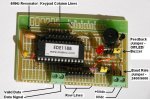
I have assembled as small circuit board using a E-Labs EDE-1188 keypad encoder.
Hardware wise, the circuit is working but it seems that the EDE1188 chip is not providing values as per the datasheet.
I first tried a small program as follows:
init: b0=0
b1=0
setint %00000000, %00000010 ; check for pin 1 going to low state
serout 7, N2400, (254,1) ; clear screen
pause 1000
serout 7, N2400, ("@") ; just so we do not have a blank screen
main: pause 10
if b1=0 then main
serout 7, N2400, (#b1) ; display the variable value as an ascii string
pause 10
serout 7, N2400, ("-") ; a spacer between each number displayed
b1=0
goto main
interrupt: serin 0, N2400,b1 ; here on interrupt when Valid Data signal at pin 1. Actual value from pin 0
setint %00000000, %00000010 ; restore the polled interupt
return
The results were that only about half the values (those in the range 3 to 63) were displayed. See attached spreadsheet.
I then modified the program to allow a value of zero to be displayed. To prevent a continual stream of zeros to the LCD module I moved the lines to display the variable value into the interrupt routine. The revised program code was:
init: b0=0
setint %00000000, %00000010
serout 7, N2400, (254,1) ; clear screen
pause 1000
serout 7, N2400, ("@")
main: b1=0
pause 10
goto main
interrupt: serin 0, N2400,b1
serout 7, N2400, (#b1)
pause 10
serout 7, N2400, ("-")
setint %00000000, %00000010
return
The revised code displayed a total of the 64 values but instead of having swequential values 1 to 64 as per the datasheet, I have 64 values in the range 0 to 127. See second table in the attached file.
I emailed E-Labs in the US directly who came back with the response:
Is was a disappointment that the output codes are intended to be 0 to 63 and not 1 to 64 as per the current datasheet, as I was hoping to:
(a) use 0 to skip any further processing, and
(b) to use the value 64 (since it is unique as only key having bit 6 set) as a latching “sticky” SHIFT flag by XOR’ing each time the value 64 was received. Then all I would have needed to do was to OR the other keypress values with the sticky SHIFT value to very quickly get the range of values from 1 to 127 to cover almost a complete set of alphanumeric values plus most punctuation/symbols on a standard keyboard using a very compact 48 button keypad configuration with 94 discrete values.
Nor are the values received at the PICAXE sequential as the datasheet suggests (See first table in the attached file).
Now maybe my aging PC (brain) is failing, because for the life of me I cannot see how to toggle bits consistently across all words as suggested by the chip manufacturer so all values are in the range 0 to 63.
I have gone back to the Australian supplier of the EDE-1188 chip and direct to E-Labs in the US but no further response overnight.
So my questions are:
1. Can anyone see/explain why the first program I wrote will not show values higher than 63 whereas the second program does. Both programs were consistent in their output to the LCD module. Note that after about 8 keypresses I reset the PICAXE each time to clear the screen?
2. Can anyone explain how I can toggle a consistent number of bits in every value to get 64 all values in the range 0 to 63?
I will be away from my PICAXE system over the weekend (but with forum access) so unable to try new code till next week but all thoughts are gratefully accepted.
Hardware wise, the circuit is working but it seems that the EDE1188 chip is not providing values as per the datasheet.
I first tried a small program as follows:
init: b0=0
b1=0
setint %00000000, %00000010 ; check for pin 1 going to low state
serout 7, N2400, (254,1) ; clear screen
pause 1000
serout 7, N2400, ("@") ; just so we do not have a blank screen
main: pause 10
if b1=0 then main
serout 7, N2400, (#b1) ; display the variable value as an ascii string
pause 10
serout 7, N2400, ("-") ; a spacer between each number displayed
b1=0
goto main
interrupt: serin 0, N2400,b1 ; here on interrupt when Valid Data signal at pin 1. Actual value from pin 0
setint %00000000, %00000010 ; restore the polled interupt
return
The results were that only about half the values (those in the range 3 to 63) were displayed. See attached spreadsheet.
I then modified the program to allow a value of zero to be displayed. To prevent a continual stream of zeros to the LCD module I moved the lines to display the variable value into the interrupt routine. The revised program code was:
init: b0=0
setint %00000000, %00000010
serout 7, N2400, (254,1) ; clear screen
pause 1000
serout 7, N2400, ("@")
main: b1=0
pause 10
goto main
interrupt: serin 0, N2400,b1
serout 7, N2400, (#b1)
pause 10
serout 7, N2400, ("-")
setint %00000000, %00000010
return
The revised code displayed a total of the 64 values but instead of having swequential values 1 to 64 as per the datasheet, I have 64 values in the range 0 to 127.
See second table in the attached file.I emailed E-Labs in the US directly who came back with the response:
Yes, I see the problem. First, I must point out that there is an error in the EDE1188 datasheet. It states that outputs are from 1 to 64. This is incorrect; they are actually from 0 to 63. This error will be corrected shortly.
However, your table appears to be exactly correct, witht he one exception that your bits are inverted. If you toggle your 1's for 0's you will notice that your third table does indeed count from 0 to 63.
However, your table appears to be exactly correct, witht he one exception that your bits are inverted. If you toggle your 1's for 0's you will notice that your third table does indeed count from 0 to 63.
Is was a disappointment that the output codes are intended to be 0 to 63 and not 1 to 64 as per the current datasheet, as I was hoping to:
(a) use 0 to skip any further processing, and
(b) to use the value 64 (since it is unique as only key having bit 6 set) as a latching “sticky” SHIFT flag by XOR’ing each time the value 64 was received. Then all I would have needed to do was to OR the other keypress values with the sticky SHIFT value to very quickly get the range of values from 1 to 127 to cover almost a complete set of alphanumeric values plus most punctuation/symbols on a standard keyboard using a very compact 48 button keypad configuration with 94 discrete values.
Nor are the values received at the PICAXE sequential as the datasheet suggests (See first table in the attached file).
Now maybe my aging PC (brain) is failing, because for the life of me I cannot see how to toggle bits consistently across all words as suggested by the chip manufacturer so all values are in the range 0 to 63.
I have gone back to the Australian supplier of the EDE-1188 chip and direct to E-Labs in the US but no further response overnight.
So my questions are:
1. Can anyone see/explain why the first program I wrote will not show values higher than 63 whereas the second program does. Both programs were consistent in their output to the LCD module. Note that after about 8 keypresses I reset the PICAXE each time to clear the screen?
2. Can anyone explain how I can toggle a consistent number of bits in every value to get 64 all values in the range 0 to 63?
I will be away from my PICAXE system over the weekend (but with forum access) so unable to try new code till next week but all thoughts are gratefully accepted.
Attachments
-
42.1 KB Views: 16