Andres Rodriguez
New Member
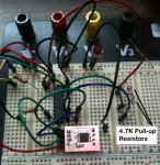
With the attached schematic and the code listed below, I write two bytes (values 0 and 1) repeteadly. When I read the data I get 255. I found a thread initiated by another member with the same problem and did no see a solution.
The memory chip is FW24W256 from RAMTRON
http://www.ramtron.com/files/datasheets/FM24W256_ds.pdf
The memory chip is FW24W256 from RAMTRON
http://www.ramtron.com/files/datasheets/FM24W256_ds.pdf
Attachments
-
17.9 KB Views: 51
-
841 bytes Views: 21
Last edited by a moderator:

") .
.