Hello, I am working with a led matrix board (24x16 leds) that I want to use with a 28X1 (firmware A.2).
The datasheet can be found on my web page (cick on Introduction).
It works very well for sending data to the matrix, but I am unable to have the 28X1 read the matrix (The board allows the user to ask the matrix if a led is ON or OFF).
There are 4 wires between the Picaxe and the matrix :
- one WRITE clock (out)
- one READ clock (out)
- one Chip Select (out)
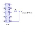
- one for DATA (should be bidirectional)
If I use one of pins 21 to 28 (= out 0 to out 7) for the DATA line, I have no problem writing to the matrix.
When I use pin 15 (in 4 / out 4) for the DATA line, with dirsc to set it as Output or Input, it doesn't work (= the matrix doesn't display anything), even when set to Output.
symbol ToMatrix = %00010000 'pin 15 = OUTput
symbol FmMatrix = %00000000 'pin 15 = INput
To write to the board, I use the spiout command, for example:
spiout WRITE, DATA, 0, (0/4)
If DATA is on pins 21 to 28, it is OK (check the small video on my page, above). If I change DATA to pin 15, and set dirsc to %00010000, the display stays OFF.
Any idea ?
Thank you,
Christophe
The datasheet can be found on my web page (cick on Introduction).
It works very well for sending data to the matrix, but I am unable to have the 28X1 read the matrix (The board allows the user to ask the matrix if a led is ON or OFF).
There are 4 wires between the Picaxe and the matrix :
- one WRITE clock (out)
- one READ clock (out)
- one Chip Select (out)
- one for DATA (should be bidirectional)
If I use one of pins 21 to 28 (= out 0 to out 7) for the DATA line, I have no problem writing to the matrix.
When I use pin 15 (in 4 / out 4) for the DATA line, with dirsc to set it as Output or Input, it doesn't work (= the matrix doesn't display anything), even when set to Output.
symbol ToMatrix = %00010000 'pin 15 = OUTput
symbol FmMatrix = %00000000 'pin 15 = INput
To write to the board, I use the spiout command, for example:
spiout WRITE, DATA, 0, (0/4)
If DATA is on pins 21 to 28, it is OK (check the small video on my page, above). If I change DATA to pin 15, and set dirsc to %00010000, the display stays OFF.
Any idea ?
Thank you,
Christophe