BeanieBots
Moderator
PE V5.2.4
PICAXE 28X V B.0
Hardware AXE091
Hopefully I've just made a silly but I can't get an external slot to run.
This is what I've tried using the AXE091 Dev board.
Fitted 24LC256 in I2C socket (tested OK in datalogger)
Connected SDA to pin15
Connected SCL to pin14
Connected pin28 (out7) to L2 (yellow LED)
Downloaded this:-
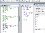
#PICAXE 28X2
#no_data
#no_table
#slot 4
do
high 0
low 0
toggle 7
pause 50
loop
followed by this:-
#PICAXE 28X2
#no_data
#no_table
for b0=1 to 6
toggle 7
pause 200
next b0
run 4
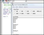
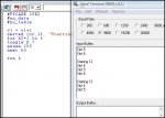
The downloads all work fine but the code in slot 4 does not run.
The LED flashes as expected due to the code in slot 0 but the 28X2 goes into the ether after the line "run 4" is executed.
It never comes back from wherever it has gone. Reset does not work.
Only a power cycle brings the 28X2 back to life.
Slots 0 to 3 work fine.
Slots 4 to 7 all give the same result.
Removing the 24LC256 gives the same result.
Download to slot 4 completes successfully even with EEPROM removed.
Any guidance would be appreciated.
PICAXE 28X V B.0
Hardware AXE091
Hopefully I've just made a silly but I can't get an external slot to run.
This is what I've tried using the AXE091 Dev board.
Fitted 24LC256 in I2C socket (tested OK in datalogger)
Connected SDA to pin15
Connected SCL to pin14
Connected pin28 (out7) to L2 (yellow LED)
Downloaded this:-
#PICAXE 28X2
#no_data
#no_table
#slot 4
do
high 0
low 0
toggle 7
pause 50
loop
followed by this:-
#PICAXE 28X2
#no_data
#no_table
for b0=1 to 6
toggle 7
pause 200
next b0
run 4
The downloads all work fine but the code in slot 4 does not run.
The LED flashes as expected due to the code in slot 0 but the 28X2 goes into the ether after the line "run 4" is executed.
It never comes back from wherever it has gone. Reset does not work.
Only a power cycle brings the 28X2 back to life.
Slots 0 to 3 work fine.
Slots 4 to 7 all give the same result.
Removing the 24LC256 gives the same result.
Download to slot 4 completes successfully even with EEPROM removed.
Any guidance would be appreciated.