Powerful IR LED driving circuit
- Thread starter Denzel
- Start date
Michael 2727
Senior Member
Yes use a transistor,e.g. a 2N700 MOSFET is good
for up to 200mA.
Many IR LEDs can be driven quite hard if pulsed for
a very brief period.
I have seen some with a Spec of up to 60mA or even
100mA I/F (Forward Current), then if you reduce the
Duty (ON Time ) you can increase the current to
double or tripple that, but it must only be a very short
pulse or the LED may explode
Of course you will need the data sheet for the device
you intend to use just to make sure.
Sony IR protocol SIRC is 38KHz, fairly fast and short
if only a single code burst is used at one time.
You could probably dump up to 500mA or more across
the LED in a 1 OFF burst and not do any harm to the
IR LED. If the LED became stuck ON for more than a
few milliseconds you could kiss it goodbye though.
I'm not saying that this will work on all LEDs so
don't take my word as gospel, for experienced users only
Most Flashing LEDs work this way, the flasher chip inside
pumps the LED with a high current, but only for a split
second.
You can see how much current if you measure it on an
Analogue Multimeter ( the ancient ones with a real meter") )
)
You may be surprised.
for up to 200mA.
Many IR LEDs can be driven quite hard if pulsed for
a very brief period.
I have seen some with a Spec of up to 60mA or even
100mA I/F (Forward Current), then if you reduce the
Duty (ON Time ) you can increase the current to
double or tripple that, but it must only be a very short
pulse or the LED may explode
Of course you will need the data sheet for the device
you intend to use just to make sure.
Sony IR protocol SIRC is 38KHz, fairly fast and short
if only a single code burst is used at one time.
You could probably dump up to 500mA or more across
the LED in a 1 OFF burst and not do any harm to the
IR LED. If the LED became stuck ON for more than a
few milliseconds you could kiss it goodbye though.
I'm not saying that this will work on all LEDs so
don't take my word as gospel, for experienced users only
Most Flashing LEDs work this way, the flasher chip inside
pumps the LED with a high current, but only for a split
second.
You can see how much current if you measure it on an
Analogue Multimeter ( the ancient ones with a real meter
)You may be surprised.
As IR LEDs need only ~1.5-1.8V supply, you can put 2 of them in series when running off 3-4.5V. This naturally hence increases system brightness, & saves you an energy sapping dropper resistor that just a single LED would require.
As visible light & IR act much the same with mirrors & lenses,also consider simple beaming techniques at both the sender & receiver. Rescued optics from toy binoculars etc (or even a page magnifier Fresnel lens) can work wonders.
As visible light & IR act much the same with mirrors & lenses,also consider simple beaming techniques at both the sender & receiver. Rescued optics from toy binoculars etc (or even a page magnifier Fresnel lens) can work wonders.
Last edited:
jodicalhon
New Member
How powerful does it need to be?
Remember that TV remotes, etc, run off only 3V and transmit over many metres. The sensitivity of the receiver is the key. Using the correct frequency, and being mindful of any other requirements like Signal Gap times, will maximise the receiver sensitivity.
Remember that TV remotes, etc, run off only 3V and transmit over many metres. The sensitivity of the receiver is the key. Using the correct frequency, and being mindful of any other requirements like Signal Gap times, will maximise the receiver sensitivity.
Michael 2727
Senior Member
While I was doing security installations it was not
uncommon to use IR Beam/Break preimeter detectors
that would span 100m or more, and in daylight.
They use a single IR Emitter/Detector @ each end.
The IR is usually pulsed @ around 2KHz, they use
lenses to focus/collimate the IR light and even have
an inbuilt optical allignment tool.
I once catalogued (stock - SAP Database) a device
at the local Timber mill which had a range of 750m
or 820 yards, I never found out where or how they
were being used, but needless to say I was impressed.
( Single IR Emitter, lenses )
Heres the scenario,
I have a robotic arm controlled by 4 servos and a DC motor sitting on top of a chunky remote control car base as seen in the picture. I ripped out the remote controls for this car and replaced them with a picaxe 08m, an L293D for the 2 motors (fwd, rev, lft, rght) and the simple IR receiver circuit shown in the manual. This is as far as I got in terms of the photo however In the circuit diagramme you can see the rest of the circuit. Which involves the axe 031 21 servo driver board, another L293D for the DC motor and a laser so that when controlling the car remotely via the onboard camera the laser points out where the arm will pick up an item on the ground. I will have two IR receivers one to the 08M for movement of the car itself. and another to the 18x on the servo driver board for movement of the arm/ laser/ claw
The problem I have is that when testing with a sony remote I have to be pointing the remote at the reciever just to get it to work, which defeats the purpose of the camera etc etc. So I guess im saying I need wireless control that can have IR bouncing off walls. I thought of having little portable 08m setups that could recieve the signal from the remote and transmit again round a corner or something.
Another problem I have is that as you can see in the picture the reciever only points to one side of the car which means when the signal comes from the other side nothing happens. Can i have lots of recievers wired in parallel all pointing in different directions.
sorry for the silly questions but im new to IR
Here is my circuit diagramme and photo:
http://i2.tinypic.com/6pz13r7.jpg Schematic
http://i19.tinypic.com/6sryzkm.jpg Photo
Last edited:
Rickharris
Senior Member
Reflection depends much on the walls and content of the room/space. It might be better to face the receiver up and put a small 08 based repeater station on the ceiling to send IR directly down to the robot.
Personally I find it better to use an 08M as the transmitter as I get more control over the output etc. Look at the Rudolph project in the Prog ed help files for a circuit and sample software.
Personally I find it better to use an 08M as the transmitter as I get more control over the output etc. Look at the Rudolph project in the Prog ed help files for a circuit and sample software.
...
I plan on using another 08M for the transmitter I just used the sony remote to test how effective the range was.
Any information on the IR recievers in parallel?
here is my idea of how it would look in a circuit diagramme...

http://i15.tinypic.com/6tk9wk5.jpg
I plan on using another 08M for the transmitter I just used the sony remote to test how effective the range was.
Any information on the IR recievers in parallel?
here is my idea of how it would look in a circuit diagramme...
http://i15.tinypic.com/6tk9wk5.jpg
Last edited:
Many people have used the receivers in parallel like this in the past. They are open collector devices (ie they short the data line to ground when active) and so there is no real hardware issues using them in parallel.
The only theoretical issue is conflicting delayed signals between 'direct' and 'bounced' light signals. However in practise this appears to be pretty negligible.
The only theoretical issue is conflicting delayed signals between 'direct' and 'bounced' light signals. However in practise this appears to be pretty negligible.
BeanieBots
Moderator
Tried and tested method. Works well.
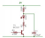
I've driven leds at 1amp. The key is to keep the the average current low as this determines the heat. So take a led and drive it from 5V with a 220R resistor and it will draw 15mA or so. Now add a driver transistor between the cathode of the led and ground eg a BC337 driven with a 470R on the base. Now add a second current limiting resistor in between the cathode of the led and the collector of the transistor - eg 3 ohms (V=IR approx 1A). This circuit as it is will still flash the led at 15mA.
Now add a storage capacitor. Put it between the anode of the led and ground. Now when you turn on the transistor the capacitor will discharge through the led at a current determined by the 3R resistor. If the pulses are kept short the capacitor will only discharge a bit and the brightness will stay high. If you pulse too often the cap will discharge. The average current can never be more than 15mA as determined by the 220R resistor which protects the led if you accidentally turn it on for too long. The charge ratio is 15mA/1000mA or 66:1 so if you pulse for 1ms you need at least 66ms of off time to recharge the capacitor.
Try it with a red led first before using an IR led, just to test it works.
Attachments
-
 15 KB Views: 92
...
Ok these IR setups work great with the receivers in parallel and the IR Led Set up Ive got quite an effective range.
My plan for controlling the servos is this:
I want the controller to have full control over every servo on the arm so Ive come up with an idea of using a 100k pot to an 08m adc pin. The 08m sends a number between 1 and 5 via IR to show which servo to control (depending on switches) then it sends the value of the pot reading. now the servos respond to numbers ~70 to 225~ and the 100k pot analog reading varies between 10 to 240 and when using the sony IR I can send 1 to 128 (as I understand)
so there are problems.
1# the sony commands don't cover the full range of the servos or pot
2# the analog reading of the pot is erratic and changes wildly which would cause the servo to jolt around
SO is there anyway to improve the analog readings from a pot so that they don't jump from 40 to 54 to 48 etc etc
and how am I to transmit numbers higher than 128?
sorry for all the questions but I find IR communication quite confusing
this was the basic transmitting code I was using as a test:
TransmitterLoop:
readadc 4,b1 'reads pot
debug b1
INFRAOUT 1,b1 'transmits pot reading
GOTO TransmitterLoop
and heres the schematic that goes with it showing the pot and IR led:

http://i3.tinypic.com/6ypjvpu.jpg
thanks
Ok these IR setups work great with the receivers in parallel and the IR Led Set up Ive got quite an effective range.
My plan for controlling the servos is this:
I want the controller to have full control over every servo on the arm so Ive come up with an idea of using a 100k pot to an 08m adc pin. The 08m sends a number between 1 and 5 via IR to show which servo to control (depending on switches) then it sends the value of the pot reading. now the servos respond to numbers ~70 to 225~ and the 100k pot analog reading varies between 10 to 240 and when using the sony IR I can send 1 to 128 (as I understand)
so there are problems.
1# the sony commands don't cover the full range of the servos or pot
2# the analog reading of the pot is erratic and changes wildly which would cause the servo to jolt around
SO is there anyway to improve the analog readings from a pot so that they don't jump from 40 to 54 to 48 etc etc
and how am I to transmit numbers higher than 128?
sorry for all the questions but I find IR communication quite confusing
this was the basic transmitting code I was using as a test:
TransmitterLoop:
readadc 4,b1 'reads pot
debug b1
INFRAOUT 1,b1 'transmits pot reading
GOTO TransmitterLoop
and heres the schematic that goes with it showing the pot and IR led:
http://i3.tinypic.com/6ypjvpu.jpg
thanks
The +5v supply rail is used by the ADC as a voltage reference. Any variations in current drain on this rail will cause slight variations in the rail voltage and therefore variations in ADC reading, even for a constant input. This could be why your reading is jumping about. I would try sourcing the drive current for your LEDs (motors, servos, whatever) from a different or somehow isolated supply. Also put a 100nF capacitor between the ADC and ground. And a couple of capacitors between the power supply legs of the PICAXE, 100uF and 100nF in parallel. The smaller will intercept the higher frequency stuff that might get through the ESR of the larger (leading edges and such.)
BeanieBots
Moderator
Your POT is 100k. That is outside the spec for a PIC ADC input.
Use a 10k POT. With 100k even connection/disconnection of the download cable may effect your readings.
Also, the advice given by Boriz will help but fix the main problem first. Don't just try to mask it.
Don't forget that cable and connections also have resistance no matter how good they are. If you have built the circuit EXACTLY as the way you have drawn it, the LED current goes down the 0v line of the POT. That will introduce errors. If you connect the POT directly to the PICAXE power pins, you will get better results.
IR transmitter
OK.
The pot is working beautiful with the 10k I have a DC motor turning exactly with the pot wirelessly with IR. quite exciting for me!
now for an effective IR transmitter...
This has been discussed and this is what ive come up with:
an IRF530 mosfet N channel run directly from picaxe 08m infraout switching two IR LEDs in series with a seperate supply voltage of 6v (2 x 3v button cells in series). The picaxe 08m and 14m runs off 4.5v (3 x 1.5v AA in series) the 14m and 08m monitor 7 digital inputs between them (7 switches) and the ADC pot reading. the 14m sends information serially to the 08m which sends it via infrared to the reciever on the 'robot'
Do the IR leds need current limiting resistors? (220 ohm)
Is this suitable as I will be sending IR via sony protocol pretty much continually
Thanks
BeanieBots
Moderator
You must use whatever series resistor will keep the LED current within spec for your LEDs.
Coin cells probably have enough internal resistance to get away without a resistor.
If you are going to be sending continuously, you might want to consider the use of an alternative power source. A typical coin cell will only have a capacity of about 100mAHr. If your average LED current is around 50mA, then they will be flat after about 2 hours.
For what it's worth, coin cells are the most expensive and least "green" form of electricity on the planet. Fine as backup and/or very low power devices such as watches but not very suitable as a continuous supply.
If you have a severe space problem which has pushed you down the path of coin cells, then consider 1/4 AAA cells. They have about 50mAHr in NiMh for a comparable volume/weight to a coin cell.
Use a 220R as you suggest. I always thought of IR leds as being very mysterious as you couldn't see what they are doing, but essentially they are just red leds with a wavelength just a bit redder than red (so they are not visible). I'll second Beaniebots re batteries. How small does this need to be? Nicads and NiMH batteries come in all sorts of sizes including the popular 3 cell packs for cordless phones.
Mycroft2152
Senior Member
The easiest way to 'see' if an IR LED is on is to look at it with a web cam or digital camera. The image sensors are sensitive to infrared light, though some may have aninfrared filter in place.
Ir Transmitter
This is a great thread! I have been working on an IR transmitter to control the WOWEE robotics products. So far I am using a NPN transistor to boost the current to the IR LED. I like the idea posted here so I will be upgrading my transmitter (Right now I have about 2 1/2 meter range)
Here is the writeup:
http://profmason.com/?p=448
The schematic is near the bottom of the page. I am only putting 100mA or so through the LED. No mosfet required.
To answer your question,the IRF530 would work fine if you have one in the junk drawer. It is way overkill for your application! (what like 14 amps!) The BC337 that was speced is rated to 500 mA and just about any power darlington will work.
Off to built the more powerful transmitter!
I couldn't get the Prof's link to work.
One thing to keep in mind when doing high power IR LEDs (or any LEDs) is that as you increase the LED current (even when fast pulsing) the Vf will increase, so that If does not increase as you reduce the Res value to LED.
If you havetime to experiment with meters and 'scopes you will find that the If and hence o/p power does not increase as much as you may think or calculate. LED Vf can increase a lot as you load up the LEDs, you may notice this when reading Data Sheets.
When using small batts insert a fat capacitor at the top side so that at least the first n pulses are juicy.
In circuit I did yonks ago I used a small R + fat C so that it reduced the HF getting back upstream - but this will only work sensibly for brief pulses.
If none of this makes any sense blame it on the sun.
This is just an additional note after previous postings.
Sorry about the link problem Dippy, it should be fixed now. We have been having major storms in the area which have made connections flakey.
I have updated my site to include an implementation of Dr. Acula's High Power IR driver.
http://profmason.com/?p=490
It seems like a power mosfet has some advantages due to its extremely low internal resistance. I agree about the current across the LED not being as simple as Vinput/Rseries. The forward voltage of the LED is a function of the current and there are these handy graphs in the LED data sheets that describe this. I suppose one could go to the effort of picking what current you wanted to run at find the appropriate forward voltage. Dividing would tell you the internal resistance of the LED at this point. Using this, plus the mosfet characteristics would tell you what size resistor you would want to use. OR.....
I just dropped a 2 ohm power resistor in there and said "Ooh it's so bright!"
have fun!
Link works. Thanks Prof.
Yes, that was what I was on about re: fat C.
That method of RC-ing can be used in many apps and also reduces noise on line.
To anyone else* thinking about a circuit like this for all apps, be aware of RC time constants etc as prolonged high power transmission pule-streams can discharge the capacitor as 220R will take a while to 'recharge' C. This will be a function of pulse lengths / duty/ duration. You can see this effect of drooping o/p power on a 'scope and you may have to vary component values depending on your specific app.
Be aware of LED power dissipation for pulsing. Newbies-Data Sheet - read!
(Or just buy a dozen spare LEDs.)
So pleased you had already read Data Sheet Prof , it's quite a rarity these days ....
*= Newbies copying circuits literally.
Re the recharge Dippy, the exact values are on page 2 of this thread and for this circuit were a charge/discharge ratio of 66:1. So just give the circuit a bit of a rest to catch its breath once it has sent some data. I also have put a red led in series with the IR led - then you can see the pulses and if the IR led ever did die (likely open circuit) the red led wouldn't light either.
Using the IRF540N
okay. I just cant get this to work.
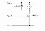
Using the example schematic in the interfacing circuits datasheet for an IRF530 (replacing the motor with an led) I can't get any leds to light! except when I change the wiring a bit so that the alternate 5v power supply for the led actully runs the picaxe aswell which would have been dangerous to the picaxe if id been using a higher voltage. Could anyone go out of ther way to draw me a little schematic using the IRF540N or correct me on the the datasheet schematic (below also) as to why it won't work... im using 3 volts to power the picaxe and 5v as the alternate power supply....
okay. I just cant get this to work.
Using the example schematic in the interfacing circuits datasheet for an IRF530 (replacing the motor with an led) I can't get any leds to light! except when I change the wiring a bit so that the alternate 5v power supply for the led actully runs the picaxe aswell which would have been dangerous to the picaxe if id been using a higher voltage. Could anyone go out of ther way to draw me a little schematic using the IRF540N or correct me on the the datasheet schematic (below also) as to why it won't work... im using 3 volts to power the picaxe and 5v as the alternate power supply....
Attachments
-
 4.1 KB Views: 42
If you are only applying 3 volts to the picaxe you will have less than 3 volts to the ifr530 gate so not much if any amperage will be allowed thourgh. Try using 5 volts to the picaxe and see if it will turn on the mosfet.
My datasheet shows only .1 amp at 25C with 3+ volts at the gate.
My datasheet shows only .1 amp at 25C with 3+ volts at the gate.
You need more voltage at the gate of the Mosfet. Typically you want an even higher voltage at the gate then between the drain and source. This "turns the mosfet on hard" meaning that the internal resistance will be a minimum. What is happening physically is that there aren't sufficient charge carriers in the channel to provide good conductance.
If you don't turn the mosfet on hard, and are trying to run a high current device it will heat up and cook!
There are special mosfet drivers if you are dealing with lots of current, but for this application, just make sure everything is running at five volts.
Here is a link to a classic dissertation on mosfets:
http://www.irf.com/technical-info/appnotes/mosfet.pdf