power issues

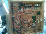
In my current project, I use a 5 volt plugpack for the picaxe, 6 volt plugpack to run servos and a 12 volt plugpack to operate toy motors and solonoids.

A 240 volt item is plugged into a 240 power board with the addition of all the various plugpacks.

I find it all very messy and space consumming as well as the plugpacks are not earthed. There is interference activating inputs when when other items are running. Could having it not earthed contribrute to this?

Is there a better way? I found this at our electronics retailer
http://www.jaycar.com.au/productView.asp?ID=MP3108&keywords=transformer+5+12&form=KEYWORD

I was thinking in future (or re-doing this project) by using one of these. Running the servos on 5v (due to there electrical noise, I am not sure if they will interfere with the PICAXE) . I would wire a 240 volt outlet onto the in side of the tansformer. This would allow me to EARTH everything easier and neater.

What do you think?

regards
Michael
 

premelec

Senior Member
You can use a multi voltage supply - however why don't you connect all the common - usually minus - plug pack voltages together - if you haven't - as the plug packs are [almost always] isolated from the 240VAC supply. If you have all of them with a common negative already and are having interference problems there is no guarantee you wouldn't get the same problems with a combined voltage supply. You'll need to add proper bypassing and isolation of transient signals. And don't have any floating inputs on ANY ICs including PICAXE.

Interference problems are a common trouble that doesn't usually show in the schematic but is found in the actual assembly and you try to localize and kill them one by one... We'd need to know more about your setup, the currents being drawn [higher currents make more intense transients] and if you've bypassed every part correctly etc. Send a picture so we can get some idea of just what a mess you've got there... :)
 

BeanieBots

Moderator
What premelec says ^^^

We have no idea of the internals of any of your plug-packs so cannot comment if they might be the cause or not. Simply using a different supply is unlikely to solve your problem. Layout, construction, decoupling and noise suppression (or lack of) should be your areas of concern. In fact, isolation from earth is often an advantage for noise problems.
 
Thanks for the quick reply

I do have all the negatives joined together
All spare inputs are pulled low
This interference problem has always been a problem. Check out the old youtube clip which gives a demonstration of the project. I have since soldered 3 capacitors on each motor and don't get the same interference, however the SD21 board (18X onboard) and the 20M still dont get on.

This is the thread about interference
http://www.picaxeforum.co.uk/showthread.php?t=16260
http://www.youtube.com/watch?v=1TZnOS8N0wo&NR=1

I now have an RIGOL DS1052E osciliscope, which I bought from dhgate.com, delivered for AUS$344. I think if I knew how to use it, it could help solve any interference problems.

Currently I do use the machine with the SD21 board turned off (I simply place the teabag in the cup). But with the crane working would increase the WOW factor.

I thought it might have something to do with earthing as the other day, the house ELCB tripped when the kettle boiled over. Nothing important seemed to get wet. Maybe a fault in the kettle.

I really started this thread for future projects, as it seems all my projects include toy motors, soloniods and servos. Just looking for the neatest safe- est, easiest and hazzle free-est solution.

regards
michael
 
Last edited:

BeanieBots

Moderator
The 'scope is a very good start.
Adding caps to the motors is a given, as is adding decoupling caps to all chips.
Assuming you've done these things already, consider layout and star connections for all the 0v lines.
A photo of your layout may well prompt inspiration for some other issues that might not come across with just text.

EDIT:
I assume you have made significant improvements since your last thread about these noise problems?
 
Last edited:
Adding caps to the motors is a given, as is adding decoupling caps to all chips.
Assuming you've done these things already, consider layout and star connections for all the 0v lines.

Sorry about the quality of the photos, but you should be able to see the power rails on the left.

Looking at the SD21 board, i dont know if there is a decoupling cap. I just put the 18x chip in. The first problem I figured out with it (with thanks to the forum) was that all the unused input pins were left floating. This resulted in the program (crane) continually going. I made a small PCB that pulls them all low when not used. This can be seen in the youtube clip listed above.

I have seperate microswitches operating the 20M and the SD21. you can see them piggybacked above the conveyor in the youtube clip.

I have tried the SD21 with a total seperate power supply, with even the negatives not connected, and it still activates the SD21 program

I have done all the usual stuff like shortening the servo leads, keeping power leads away from signal leads, however have found those things to make no difference.

The caps on the motors are 104 polyester

regards
michael
 

Attachments

premelec

Senior Member
Ah so... so many opportunities for problems there! I would first put capacitors right on the motors which seem to be generating the interference - and use .2uF and perhaps 10uF electrolytic as well [if not going in forward and reverse - ] and put some small resistors in series with the leads to the motors - not enough to slow them much but enough to absorb the hash from the motors. And DO learn to use your 'scope - you'll be glad you did [or be horrified at what you see...]. Anyhow start cleaning things up and bypassing better and soon it'll sort out... You may have to put in some inductors in series with the motors as well. I see relays - do they all have back across them?

Start looking at the electric hash on the motor lines with the oscilloscope and make it go away where it goes all the way back to the control board - kill it AT the motor. You are well on the way... persist and calm it out! :)
 

MartinM57

Moderator
I now have an RIGOL DS1052E osciliscope, which I bought from dhgate.com, delivered for AUS$344. I think if I knew how to use it, it could help solve any interference problems.
Do you understand the basics of using an oscilloscope and have you tried using it yet? You have an ideal problem for using the oscilloscope to sort out!

This is the first of a reasonable (*) set of intro videos worth spending a bit of time watching - the guy covers things quite quickly so you might be pausing and winding it back a lot!
http://www.youtube.com/watch?v=qIfo_-d82Co

(*) - if I heard him right, he doesn't understand x1 and x10 probes properly and what he says about using a x1 probe normally is wrong - use a x10 probe normally
 
Last edited:

Dippy

Moderator
Wise advice.


"I think if I knew how to use it, it could help solve any interference problems. "
- I suggest you read the MANUAL and have a go! Dear Lord.
Just be aware that some 'scopes can affect the signal in a high impedance circuit and the noise may not be so apparent.
Test No. 1 : Quality of power getting to each chip/board.


You have about 10 feet of 'antenna' just asking to pick up noise. Cut it down. Assuming you have no fast signals then a bit of decoupling (aka bypassing) may help.
And NEATNESS is key to a good build. That's a plate of spaghetti.


Do you know:
1) ... what decoupling means? And the best choice of capacitor?
2) ... what 'star' connections means?
Please be honest.


Are you using low-sided switching for the relays?
i.e. a NPN tranny (or N chan MOSFET) between relay and ground?
If so, put a 100uF low-Z electrolytic capacitor on the positive side of the coil (to ground obviously).
This reduces the SURGE in the supply line when the relay is triggered.
AND it absorbs most of the oomph shoved back due to the back EMF diode which will, of course, be fitted.
Does this make sense?
Please be honest as it's handy for us to assess your skill/knowledge level.


And, don't forget, sometimes screening is the only solution.
Good luck.
 

MFB

Senior Member
It may be worth running the PICAXE from a supply that is completely isolated (separate grounds) from the motor supply, but this will of course require opto-couplers between the both circuits.
 

gengis

New Member
Servos (anything with a DC motor) require a LOT of current to get them turning. Until they are turning, they appear as a near-short circuit to the power supply, which will cause a sudden drop in voltage to the picaxe.

Switch mode power supplies have very small capacity output caps - they don't require a lot to eliminate high frequency ripple, but your circuit may benefit from having a large cap to draw from while the motors start turning.

Beef up the capacity - and pay attention to grounding. Heavy current through wires causes drops along the length of the wire - not necessarily a big deal for a digital circuit, but it can play havoc with an ADC input. The heavy current paths should connect closer to the source of power than the analog and processor power wiring.

Isolating Diodes and Capacitors can also be used with good effect to keep the processor up and running when the voltage to the rest of the circuit is drooping with a sudden load.

If you have test equipment connected, they can introduce problems with ground loops. For instance if the negative of the supply is grounded to the power line and your scope is also grounded through the power receptacle you may be introducing another path for current to take. And all manner of problems if they are on two different mains circuits.
 

cdngunner

Senior Member
My two pennies worth from having similar problems.

Neatness, grounding, isolation and shielding can go a long way to reducing unwanted noise.
 
Top