Pot matrix

hippy

Technical Support
Staff member
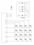
Imagine an 18X Led matrix, diodes pointing out on the row drives, diodes pointing in on the column drives; any single Led can be selected by having one row high the others low, one column low the others high, now ...

Replace the nodes with 10K pots, all with their wipers joined feeding a single ADC input via a diode ( giving a 0V to Vpsu-Vdiode input ). That's a 4x4, 16 pot multiplexor. The 18X has three ADC's so let's go for three pots per node, each feeding a separate ADC; a 48 pot multiplexor.

I'm not too worried about a little noise pick-up or having to have some small dead-zone top and bottom to get a 0-255 result from each pot.

Can anyone see any problems I've overlooked ?

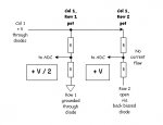
Added : I think each pot will need a pair of diodes, one at each end.
 
Last edited:

BeanieBots

Moderator
Haven't fully pictured the layout, (maybe some ASCII art?) but I can't quite see the point either!
You've 8 outputs, so potentially 255 LEDs could be used as indicators.
Four inputs with push buttons (two sets of inc & dec) to cycle through each "virtual" pot and set their values.

256 pots, full resolution (16 bit if you wanted), with smaller component count.
Maybe I've missed something?
 

hippy

Technical Support
Staff member
I think you may have missed something; these are real physical pots, the Led matrix was just to set the scene. I need an easy way to multiplex 48 pots and this seemed a good single chip solution.
 

Tom2000

Senior Member
Hippy, I can see the matrix of 16 pots to a single ADC working. But for the same thing working to feed 3 ADCs, I don't see it. It seems to me that you'll have to parallel 3 pots on each matrix node to make this happen. And those three would interact.

This is just off the top of my head. I'm going to fire up Word and do some sketching to try to figure this out. Who knows... it might work with three diodes per pot. Or it might not.

I'll get back to you. Hopefully with 8x10s with circles and arrows, and a paragraph on the back of each one.

Tom
 

BeanieBots

Moderator
I got the bit about real pots. The bit I missed, was why.
The pots are read by the ADC input. So the PICAXE does something with the value. Something it could do equaly well (if not better) with an internally generated value. The internally generated value could be set and displayed using push buttons and LEDs.
If however, the analogue signal needs to be fed to some other circuit (but you did state 18X analog input) then it would be a different matter.

I've not had a chance to sketch it out but in my head I see loading of the wiper by the other pots even with the diodes. I could be wrong. I'll get back.
 

andrew_qld

Senior Member
Interesting idea. I have just been scribbling it out on a piece of paper as it's a little hard to visualize and harder to explain in words.

It's workable.

I think you would need a diode at one end of the pot and also on the wiper. Otherwise you could have current flow from one wiper, through the second pots wiper.

What I mean is, if the pot you are measuring has its wiper very close to the +V end, and the next pot on that column is very close to the earth end then the path of least resistance for the current will be out through the first pots wiper to ground via the second pots wiper.

I'd jury-rig a 2x2 matrix and check it on breadboard first, but I think it would work.

Andrew
 

BeanieBots

Moderator
I've come to the same conclusion.
Diode on the top and out of the wiper.
Certainly would work for 'simple' common ground multiplexing but full matrix I'm still head-scratching without pen & paper.
 

Tom2000

Senior Member
OK.... I think I have it.

Hippy, had we been chatting over a stout in a pub and you told me, "Tom, I think I can mux 48 pots with an 18X!" I probably would have told you that you were out of your mind. (Of course, that would depend upon how many stouts we'd shifted before your statement. :) )

But your idea of beginning the thinking with a diode matrix was the breakthrough that made the analysis workable.

Constructing a cell that looks like a diode to the column and row selection lines, but still provides isolation to the ADC busses, is the answer.

I've attached a sketch that I think would work. Everybody think about it and see if your can shoot holes in it. And see if you can get the diode count below 80.

Now I'd *really* like to know what you're doing that requires 48 pots??????

This stuff is fun!

Tom
 

Attachments

Last edited:

Tom2000

Senior Member
My solution won't work.

Let's say you're addressing column 1, row 1.

All column outputs are low except for column 1. And all row outputs are high except for row 1.

The high on column 1 will enter all column 1 cells, feeding the proper pot outputs to ADCs 1, 2, and 3 from cell 1,1. (Since the 1,1 cathodes are grounded, the cell1 pots will act as proper voltage dividers.) But it will feed a naked 5 volts (minus diode drop) from the rest of the pots on column 1 to the ADC busses, swamping the readings from the col1, row 1 cell. (With the floating cathodes on the rest of the col 1 cells, very little current will flow, thus very little voltage drop through the non-active pots.)

Back to the drawing board.

Edited to add: Hippy, I don't see a solution to the swamping problem. I don't think multiplexing pots, even 16 into a single ADC, is workable.

Sorry,

Tom
 
Last edited:

Tom2000

Senior Member
Swamping Problem

The sketch below illustrates the swamping problem I described above, and illustrates why pot multiplexing won't work.

I've shown only two pots, col 1/row 1 and col 1/row 2. For the purpose of this illustration, I haven't shown the cell anode and cathode lead diodes.

In this illustration, the col 1/row 1 cell has been selected by placing a high on the col 1 lead, a low on the row 1 lead, and a high on the row 2 lead.

The col 1/row 1 cell is properly connected. The top side of the pot is connected to +V, and the bottom is connected to ground. For col 1/row 2, the top of the pot is also connected to +V. but the diode at the bottom of the pot (not shown) isn't conducting, since there is a high on both ends of the cell.

The +V into col 1/row 1 causes current to flow through the pot. If it's set for 1/2 resistance, 1/2 of the voltage will appear on the wiper and will be fed to the ADC bus.

Since the col 1/row 2 pot isn't grounded, negligible current will flow through it. There won't be any voltage drop across the pot. Therefore, the full +V value will be fed to the ADC bus.

Since the ADC input is very high impedance, the +V from the wiper of the col 1/row 2 pot will swamp the +V/2 from the wiper of the col 1/row 1 pot.

Therefore, pot multiplexing without something like 4066 switches in the wiper of each pot won't work. Simple diode steering isn't a viable solution.

Tom

Edited to add: I might have been too quick to dismiss the 4066 solution. Although that would add a dozen chips plus whatever else was needed to address them, when you're speaking of a 48 pot setup neither size nor cost is important. It requires a totally different outlook than I'm used to in order to perform an engineering analysis on a system such as this.

Hey, look at the bright side. That dozen 4066 chips would eliminate 48 diodes! :)
 

Attachments

Last edited:

BeanieBots

Moderator
I'll take your word for it but one pot per output will work with just a single diode on each pot's wiper. Diode OR'd into the ADC input with a high value pull-down.
With a little more logic to expand the 8-bits to 256 singles it would be possible to expand to the full 256 pots.
 

moxhamj

New Member
16 pots - I am wondering what this could be for as I recall seeing once an article on pseudo medical devices that can read your stress/honesty/inner karma etc and they had things like a couple of probes one held in each hand and a very impressive array of knobs on the front. Only trouble was that when the electronics magazine pulled the device to bits they found none of the knobs were actually wired up. So if it is this sort of use it could save lots of time if the knobs don't need wiring ;)

A couple of 4051s would work for 16 pots. Would use one ADC and 4 output lines. Or 2 ADCs and 3 output lines.
 
Last edited:

hippy

Technical Support
Staff member
Thanks everyone, and I'm glad it wasn't just me having problems visualising it or proving it could / wouldn't work. I think Tom2000 nailed the fatal flaw and his attached diagram illustrates the problem. Diodes on the wipers won't help.

Bummer, but never mind. With 8 outputs each driving one pot all with diode-mixed wipers I can scan 8 pots, and with 3 ADC's that's 24 pots. Can use two 18X's instead of one and a bit of synchronisation, or go to a 28X1 which would allow 16 x 4 ( 64 ).

48 pots - I have a lighting desk prototype which was diverted from the skip, metal work with faders attached, and thought it would be fun to get back into doing some DMX. I don't need all 48 pots but thought I may as well turn the buttons into resistor ladder 'pots' as well.

4051/4066 multiplexors will work ( how it was done when I was working on desks ) but as always I was after the simplest, buy nothing extra to what I have, solution.

One thing I've found while playing with other, arguably better, micros than the PICAXE, is that I really do miss Analogue inputs on-chip when they're not there. Until they're not there it's easy to forget how useful they are.

Dr_Acula : Just because the pots were not wired up doesn't mean the 'karma machine' didn't work ;-)
 
Last edited:

Tom2000

Senior Member
Hippy, here's another idea.

Build 3-pot cells, with the wiper of each connected to one ADC bus through a diode.

Ground the bottoms of all the pots.

Drive the top of each cell with an output taken from a 74xx595. If my thinking is right, the 595 would power each cell, one at a time.

This would do the trick with 48 diodes and 2 595 chips.

Tom
 

hippy

Technical Support
Staff member
I've been doing some more design and similar to what Tom2000 sugests with 595's but with PICAXE's only. Because the 08M, 14M and 18X ( with some SFR poking ) can have a variable number of analogue inputs it's possible to balance digital outputs against analogue inputs for a maximal matrix at lowest costs.

An 18X can handle 35 pots ( 7D x 5A ) but a 14M should handle 25 ( 5D x 5A ), at less than half the price. Two should handle 50 pots but, with slightly more complex comms, 100 pots may be possible ( 10D x 10A ). Beyond that, a 28X1 or 40X1 is more cost effective and also better suited if one wants to do processing rather than just pot scanning and sending.

I haven't actually done any 14M experimenting and it's been rather neglected compared to my pushing other PICAXE's to their limits. So this is currently theory but I cannot see it not working.

One thing I have realised is, with diode mixing of pot outputs, that creates a considerable dead band at the bottom of all the pots equivalent to the diode voltage drop. All pots on the same digital output have to have their bottoms connected to a common 'virtual rail' connected to 0V via a similar voltage drop diode, or each pot connects to 0V via its own diode which means more diodes but can make wiring up easier.
 

Tom2000

Senior Member
I thought about the deadband problem, but figured that since it's for a lighting app, that wouldn't cause a problem.

I think your idea of lifting the pot common rail one diode drop above 0V to compensate for the diodes in the wiper circuits is downright clever, Hippy. One cheap part eliminating the whole deadband problem.

Nice!

Tom
 

hippy

Technical Support
Staff member
I wasn't sure if dead band would be a problem or not either, but that translates to ~10%, 6mm travel on a 60mm slider ( probably tolerable ), 27 degrees on a 270' rotary pot which is a bit more noticable.

I considered a single diode for all pots but the pots pulled down to 0V, all in parallel, will probably pull down the virtual rail. Anther concern was using pot values high enough not to overload the PICAXE outputs; but even 10 x 4K7 in parallel is only 470R, ~10mA.
 

Tom2000

Senior Member
I considered a single diode for all pots but the pots pulled down to 0V, all in parallel, will probably pull down the virtual rail...
You'll only be powering one cell at a time, so that shouldn't be a factor. I think one diode should do it for the lot.

Good luck!

Tom
 
Top