alexthefox
Senior Member
in witch way can i drive pnp transistor with picaxe?
drive npn and with that drive a pnp?
drive npn and with that drive a pnp?
thk, but i did with npn like manuals and i work fine. i just ask if i can drive with pnp.OK, since I didn't see an example in the manuals.
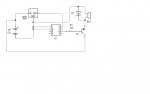
This is an illustration of a PNP driven directly off the PICAXE for a 5v LED/resistor load, and through a NPN/PNP combination for a 12V lamp.
For a 12V buzzer, you can drive an NPN from the PICAXE, through a bias resistor, with the emitter to common, the collector to the buzzer, and the buzzer to +12v (examples in the interfacing manual). Make sure you add a diode across the buzzer...cathode (band) to +12.
Ken
 )
)And hasn't KMoffett shown how to do it with a PNP ?thk, but i did with npn like manuals and i work fine. i just ask if i can drive with pnp.
yes, i didnt put just to post a quickly diagramNo. That won't work.
As I said earlier, if you want to run the PICAXE from 12v and only use a single transistor which is PNP then you will also need a negative regulator such as 7905. The ENTIRE circuit has to be positive ground as I described. Your option is to either buy a 7905 or use a NPN tranny.
You also left the decoupling caps and regulator caps off your diagram!
Don't forget that serin also needs to be tied to ground if the programming circuit is not used.
that is 7905 and not 7805. anyway wrong?No. This is becomming painful!
YOU CANNOT USE A PNP TRANSISTOR AND HAVE 12v.
EITHER, run the buzzer from 5v AS SHOWN BY KMoffet's diagram.
OR use an NPN to drive the PNP AS SHOWN BY KMoffets's diagram.
OR run the PICAXE from a negative supply AS DESCRIBED BY ME.
You can't run a petrol car on diesel either.