PICAXE turned on/off by PTM button

wob_b

New Member
Would this kinda of idea work? i know i might need another resistor here and there, and not too such about the resistance of the 1 ive put in.


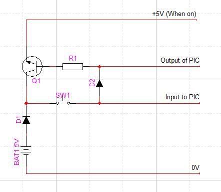
Basically, you press the PTM button, which turns on the transistor, effectivly turning the circuit on. As long as the output pin connected to the transistor is high, then the circuit stays on. Another press of the button, or other kind of trigger, the output goes low, turning everything off - saving battery life.

Im sort of new to picaxeing, but havent seen this mentioned anywhere in the reseach ive looked at. Wondered whether it would work.

Wob_b
 

Dippy

Moderator
Have you tried it?
This has been covered many, many times includng just recently but blowed if I can find it.

If you have sorted the one-transistor method then you will receive a Gold Badge.
 

moxhamj

New Member
The theory is right - it will work and will keep itself on. The transistor is wrong though - you are using a NPN transistor (arrow coming out of the transistor) and for high side switching (ie switching the 5V) you need a PNP transistor (arrow going into the transistor). Also D2 will zap the picaxe - it isn't needed. Finally, this sort of circuit can easily do a "push to turn on", but the second push to turn off is much more complicated (see above links). As an aside, you don't need to turn picaxe circuits off anyway - put the picaxe into low power mode (low clock, disablebod, sleep) and it uses less power than the batteries' self discharge rate, ie it will last practically the same as the batteries would have lasted in their unopened packet. Isn't that a nifty feature of the picaxe!
 
Last edited:

Mycroft2152

Senior Member
As an aside, you don't need to turn picaxe circuits off anyway - put the picaxe into low power mode (low clock, disablebod, sleep) and it uses less power than the batteries' self discharge rate, ie it will last practically the same as the batteries would have lasted in their unopened packet. Isn't that a nifty feature of the picaxe!
This also makes the PICAXE great for solar powered projects!

Myc
 
Also D2 will zap the picaxe - it isn't needed.
Please correct me if I am wrong, but D2 is necessary to switch the transistor on, allowing for the 5V supply to reach the power pin of the picaxe.

I do not know about concerns of 'zapping the picaxe' but if this is the case, a third diode could be added from the output pin, preventing the current from entering the chip through this pin.

That asside, the concept looks very good, and I shall try it out if I can, and see what I come up with. I shall let you all know later (hopefull)
 

moxhamj

New Member
Please don't put D2 in as such. Say the output of the picaxe is set low, which it will be when it first boots up. Current will flow directly from the battery through both diodes, albeit with a 0.6V voltage drop on each diode, and directly into the output pin. The chip will end up getting hot as that current is only limited by the internal resistance of the batteries.

Yes, you could add another diode if you wanted. But it is getting a bit more complex than it needs to be. You could, for instance, leave out D1 and D2, use the proper PNP transistor eg BC557, and put the switch directly across the transistor. Also leave out any connection to the input of the picaxe. Push the button to turn on, and then keep the transistor on by keeping the output pin low (yes, low, as this is a PNP transistor). Turning itself off is very hard - probably impossible with one transistor as lots of people brainstormed this on the forum not long ago and I don't think we came up with an answer.

But I think the next thing is to start breadboarding circuits. Please let us all know how you get on in the next few days :)
 

sghioto

Senior Member
The one xistor PNP will not work. The Picaxe output pins have a low enough internal resistance to ground to bias on the PNP xistor when no power is applied. Circuit will power on immediately when the battery is connected. Have verified this on a breadboard a long time ago.
Wob_b your circuit will not stay on when the button is released because the output from the Picaxe will always be slightly lower then the voltage on the emitter. In other words the xistor will not receive enough bias from the output pin. The NPN requires a base voltage .6 volt above the emitter to turn the xistor on.

Steve G
 
Last edited:

Peter M

Senior Member
Would this kinda of idea work? i know i might need another resistor here and there, and not too such about the resistance of the 1 ive put in.


Basically the circuit you have here wont work aside from D2.

At bat1 you have 5v, at cathode of D1 you have 4.4v, therefore the max output from picaxe = 4.4v, at B of Q1=4.4v, at E of Q1=3.8v, therefore the max voltage is now 3.8v..... apply that to Q1 base so on and so on.... so even theoretically impossible in a perfect world.... which I do enjoy living in??

But don't give up, there is a gold badge on offer! :D

Even with an PNP transistor the leakage through the picaxe when off, turns the transistor on, keeping the circuit on, yes many have tried 1 transistor, even myself (doubting Thomas), so if you can crack it, much applause will come your way.
 

inglewoodpete

Senior Member
I haven't tried to work out if this circuit would work. I haven't the time but the transistor must be a PNP and the emitter would connect to the +ve end of the battery. It would help if the drawing had the +ve power rail (+ve battery lead) at the top of the drawing.

But it's late and I can't think straight....
 

Dippy

Moderator
Yes, wobert, feel free to dabble and experiment. It's great learning.
May I recommend, as variations on your circuit have used more Forum space than nesbit, that you have a good bread-boarding session and post your results.
Basically, I'm pretty certain your circuit won't achieve the desired results. But a twiddle here and a twiddle there and well, you never know.

Please keep at it though and you'll learn that there is more to transistor switching than you think. And, if you get a result, then you can post with pride rather than just saying "what happens if I do...?"

Please note that every man and his brother have made a two transistor version. And Steve G made a version with a single component didn't he?? (Didn't you Steve?). But I can't remember what it was.

Oh, and if the solution uses a clunky relay, don't post it :) as much of the previous debate was around micropower circuits.


PS. The Spammers are getting very cunning. AshleyJoseph. Seems to have moved from China to Karachi, Sindh, Pakistan ISP: Multinetbroadband. And picked a nice innocent sounding name too!
 
Last edited:

Dippy

Moderator
Can't get the link to work BCJ.
But if it's the one I'm thinking of then it's just as complicated a two-transistor solution.
 

BCJKiwi

Senior Member
Fixed the link.
Yes it's the same one we discussed before. I know you think it's more complicated but I beg to differ, and gave my reasons before.

However I am not interested in a competition. This is a thread looking for a single transistor solution and the Microchip circuit provides that.
 

boriz

Senior Member
Forgive me if this is obvious and/or old hat, but as an alternative, couldn’t you just use a simple push-to-BREAK momentary button in the +5v supply, with the code executing a SLEEP command after it’s done it’s job? If there is a problem sourcing such a button, any salvaged microswitch will work.

The PIC spends most of it’s time in SLEEP, but when the button is pressed, power is removed and then returned, resetting the PIC and restarting the code.

With a little extra code, the same switch could work as a push-on/push-off switch. Simply have the PICAXE begin the program with an EEPROM check. If the location contains zero, then change it to one and continue to run the rest of the program. If the location contains one, change it to zero then SLEEP. A variation of this method could drive the program through several modes or functions depending on the number stored in the EPROM, making the last mode the off mode (SLEEP).

EG:

PICAXE is PWM driving a power LED on a camping lamp.

Mode zero = off. (EEPROM contains zero)
Mode one = 20% PWM. (EEPROM contains one)
Mode two = 60% PWM. (EEPROM contains two)
Mode three = 100% PWM (EEPROM contains three)
One more press resets the mode to zero and SLEEPs the PICAXE.
 
Top