[RESOLU] PICAXE Syntax - First Use

ASCO

Member
Hello everyone,

Get ready, my story is quite complex x)

I belong to a company that owns PB-3B microcontrollers from Compile Technologies. We use a laptop running XP to program these microcontrollers (PB-3B) with an old board. Today, I would like to switch to PICAXE with the PICAXE Experimenter Board (PICAXE Store) and the AX027 cable. I have these products because we configure another type of microcontroller (PIC18F14K22).

According to my discussions with PICAXE, I need to change microcontrollers to use the PICAXE Editor 6 software. They recommended the PIC18F25K22.

My problem: I have syntax issues in my program. The original software is PICBASIC, and the commands are different. Unfortunately, I know nothing about programming, especially coding, so I need your help to adapt my program to use it with PICAXE.

I am attaching the original program and the program I started modifying.

If a kind soul could help me, I would be very grateful.

Thank you in advance.
 

Attachments

radiosparks

Active member
Here's my initial view of your code - My 2 cents worth. Google helped with the translation.

First Issue - Program line LABELS - Labels cannot start with a number -

"QUOTE from MANUAL
Labels can be any word (that is not already a reserved keyword) and may contain digits and the underscore character.
Labels must start with a letter or underscore (not digit), and are followed directly by a colon :)) at the marker position. The colon is not required within the actual commands. The compiler is not case sensitive (lower and/or upper case may be used at any time).
";

Second - Many Functions are undefined -

Rich (BB code):
Code Snippet - Example
    high 11           ; Proc?dure d'autoz?ro
    high b.5
    LCDINT             ; function not defined - setup to initialize LCD
    csroff             ; function not defined - unknown
    locate 4, 0        ; function not defined - character position on the LCD display
    lcd "autozero"     ; function not defined - print at location this text
    csroff             ; function not defined
    pause 10000
    low 11
    goto 1             ; Labels must start with an underscore or letter

1:
Once these issues are resolved the program can be further refined to run on a PICAXE.
 

cpedw

Senior Member
Another thing to watch is that byte variables and word variables use the same space so w1 uses b2 and b3. I recommend
Code:
'symbol ZERO1 = w1       ; Z?ro de la grande ?chelle
symbol ZERO1 = w11       ; Z?ro de la grande ?chelle
'symbol ZERO2 = w2       ; Z?ro de la petite ?chelle
symbol ZERO2 = w12       ; Z?ro de la petite ?chelle
'symbol x = w3           ; Calcul en ppm
symbol x = w13           ; Calcul en ppm
unless you intended that these word variables should be made up of I,R,HE,P,CAL.
 

AllyCat

Senior Member
Hi,
I need to change microcontrollers to use the PICAXE Editor 6 software. They recommended the PIC18F25K22.
Welcome to the forum. Note that you MUST use a "genuine" PICaxe (presumably now the 28-pin PICAXE-28X2) which is pre-programmed with the PICaxe Basic interpreter, not just any "off-the-shelf" PIC18F25K22. The 28X2 is normally supplied marked with the "base chip" number PIC18F25K22 (see HERE), but only a PICAXE supplied by the PICaxe Store or one of their distributors can be used with the Program Editor (PE6).

PE6 can also be used with the 20-pin PICAXE-20X2 (labelled PIC18F14K22) but the 28X2 has a few more software features (and of course 8 more pins).

Do you have any more information about the connected Hardware, in particular the LCD, because the exact pin connections are going to be very important.

Cheers, Alan.
 

Flenser

Senior Member
ASCO,

I haven't ever heard of this PICBASIC-3M module before. If I have found the right one then they are manufactured by the Korean company COMFILE Technology and appear to have been distributed in France.

Would you confirm for the rest of the forum members that:
- this is the PB-3M module that you are using: https://www.lextronic.fr/microcontroleur-picbasic-3b-459.html
- this is the PICBASIC language you are using: https://www.lextronic.fr/lextronic_doc/PICBASIC.pdf

The only information about these modules I could find on the web was either in Korean or French.
Do you have the PICBASIC language manual in English as it will be easier for the English speaking forum members to use than google translate.

I see that you've asked the French forum about this too. If you google picbasic you will get hits for the compiler sold by ME Labs and Microchip for Microchips PIC microcontrollers so you you should post the link to the COMFILE PICBASIC manual to that thread so they know which PICBASIC you are referring to.
 

Flenser

Senior Member
ASCO, as you are new to the PICAXE I plan to include a fair amount of background info so I won't cover all the conversion in one go, I'll do it in a few posts.
I'll also limit my comments to just what you need to use to convert your program. My intention here is to avoid adding any unnecessary, and possibly confusing, extra details that are not relevant for the task to convert your program.

Starting at the top of your program.

The constant that defined the device type 3B:
CONST DEVICE =3B
Needs to be changed to the "#" preprocessor directive that declares that this program is to be compiled for the 28X2 chip:
#PICAXE 28X2

The default frequency for for the 28X2 chip is 8MHz but I usually explicitly set the clock frequency in my PICAXE programs with the SETFREQ command.
- This will be important when you convert the DELAY and BUSOUT commands.

Add this command to run the 28X2 chip at 8MHz using the internal RC oscillator.
SETFREQ M8

The PICAXE Experimenter Board has an 8MHz resonator installed for the X2 chips but by setting M8 means it simply won't be used.

Declaring variables and constants
Les variables de type "BYTE" qui pourront correspondre à un nombre compris entre 0 et 255 (elles occuperont 1 octet de mémoire RAM) et les variables de type "INTEGER" qui pourront correspondre à un nombre compris entre 0 et 65535 (elles occuperont 2 octets de mémoire RAM).
- a PICBASIC byte is a PICAXE byte variable that can contain the values 0-255
- a PICBASIC integer is a PICAXE word variable that can contain the values 0-65535

The PICAXE variables are distinctly different from the PB-3M variables.
- The PICAXE variables are predefined.
- As cpedw has already pointed out byte variables and word variables use the same space.

I recommend that you read the section "Variables - General" in the manual "Section 2 - BASIC Commands" that you can download here: https://picaxe.com/getting-started/picaxe-manuals/.
If it is more convenient for you the PICAXE commands are also available online here: https://picaxe.com/basic-commands/

This page https://elecurls.tripod.com/pmr.htm is written for the smaller 08M2 PICAXE chip but the way that the PICAXE byte and word variables share the same RAM space is the same for all PICAXE chips and the first section in this page has a diagram illustrating this.

You've converted all the PBASIC byte variables to PICAXE bN variables and most of the PBASIC integer variables to PIXAXE wN variables.
However, "DIM batt as integer" is converted into "symbol batt = b0". Is this a typo?

In Proramme en cours.bas you have written:
Code:
symbol I = b2           ; Choix du type d'?chelle selon l'interrupteur entr?e 2
symbol R = b3           ; Correspond au bouton autoz?ro entr?e 1
symbol ZERO1 = w1       ; Z?ro de la grande ?chelle
This is what cpedw was referring to. With these definitions when you alter variable I you also alter the low byte of variable ZERO1 and when you alter variable R you also alter the high byte of ZERO1 which is probably not what you intended.

The coding technique I use is to declare all my byte variables first, then my word variables, like this.
Code:
symbol V = b0         ; w0
symbol I = b1           ; w0
symbol R = b2         ; w1
symbol HE = b3      ; w1
symbol P = b4         ; w2
symbol CAL = b5    ; w2
My byte variables have used the RAM up to w2 so I need to start my word variables at w3:
Code:
symbol batt = w3             ; b6:b7
symbol ZERO1 = w4       ; b8:b9
symbol ZERO2 = w5       ; b10:b11
symbol x = w6                  ; b12:b13
DELAY 100
changes to:
PAUSE 100

NOTE this will only be correct at a clock frequency of 8MHz on the 28X2 chip. See the PAUSE command in Manual to for a description of how different CPU frequencies effect the DELAY command.


OUT Port, Val
My understaning from the translated French is tht the PBASIC Port value is the I/O number. e.g. the out 9,1 command sets the PBASIC I/O9 pin high
PICAXE BASIC used a PORT.PIN syntax.
- The 28X2 chip has three ports A, B & C. Port A has PINS 0-4 while PORT B & C each have PINS 0-7. e.g. A.1, B.2, etc

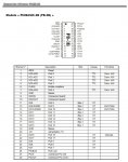
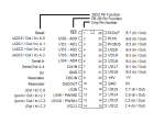
I have prepared this diagram showing my understanding of the way PBASIC and PICAXE name the 28 pins on the PB-3B and 28X2 chips.
26065
The OUT PORT,1 and OUT PORT,0 commands can be converted to the PICAXE BASIC commands HIGH PORT.PIN & LOW PORT.PIN

So thesxe commands:
out 10,1
out 10,0

become:
high C.2
low C.2

The colon[:] character operates exactly the same. It can be used to seperate multiple commands on a single line.
So this line:
out 10,1: delay 100

can be coded as:
high C.2: pause 100


There is one problem I don't have an answer to.
Your "Programme initial.bas" includes out commands for the PBASIC pins I/O5, I/O6, & I/O7 but the Pinout Diagram I found for the PB-3B chip does not show any such pins.

Other than this problem you should be able to:
1) Convert this first section of your code
Code:
CONST DEVICE =3B

DIM batt as integer    'valeur batterie entrée 0
DIM V as integer    'valeur de sortie helium pour écran
DIM I as BYTE        'choix du type d'échelle selon interupteur entrée 2
DIM R as BYTE        'correspond au boutton autozéro entrée 1
DIM HE as integer    'valeur sortie d'AOP = signal amplifier du cataro
DIM P as BYTE        'démarrage de la pompe pendant l'autozéro sortie 11
DIM CAL as integer
DIM ZERO1 as integer    'zéro de la grande échelle
DIM ZERO2 as integer    'zéro de la petite échelle
DIM x as integer        'calcul en ppm

    '================= TEST leds ==================== 
    out 10,1: delay 100
    out 10,0: delay 100
    out 9,1: delay 100
    out 9,0: delay 100
    out 12,1: delay 100
    out 12,0: delay 100
    out 13,1: delay 100
    out 13,0: delay 100
    out 14,1: delay 100
    out 14,0: delay 100
    out 15,1: delay 100
    out 15,0: delay 100
    out 16,1: delay 100
    out 16,0: delay 100
    out 17,1: delay 100
    out 17,0: delay 100
    out 5,1: delay 100
    out 5,0: delay 100
    out 6,1: delay 100
    out 6,0: delay 100
    out 7,1: delay 100
    out 7,0: delay 100
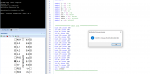
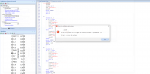
2) Open your converted program in the PICAXE Program Editor and check the program using the menu item "PICAXE -> Check Syntax"
3) Plug your 28X2 chip into your Experimenter Board
4) Connect up LEDs and current limiting resisters to their pins on the 28X2 chip
5) Power on the Experimenter Board and connect the AX027 cable to the PC
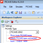
6) Check that the Program Editor can communicate to the 28X2 chip using the "Check PICAXE type connected" link
26066
7) Download the program into the 28X2 chip using the menu item "PICAXE -> Program" and test that is works to flash each of the LEDS at the right speed.


There are a lot of LCD statements, like LCDINIT, PRINT, CLS, BUSOUT in your program so this is what I will check next.

However, these commands are all coded to communicate to the Comfile Technologies ELCD Serial LCD module so I can't start this until you tell us which LCD module to you plan to use with the 28X2.

So long as you plan to use a serial LCD module it doesn't matter which one you choose but as the modules sold by different companies can use different serial protocols you will need to use code that is specific to the module you choose.
 

Jack Burns

New Member
Flenser - Excellent information to get ASCO started.
There is one problem I don't have an answer to.
Your "Programme initial.bas" includes out commands for the PBASIC pins I/O5, I/O6, & I/O7 but the Pinout Diagram I found for the PB-3B chip does not show any such pins.
I've just spotted the missing pins are shown on page 12 of the manual you linked to earlier:
Would you confirm for the rest of the forum members that:
- this is the PB-3M module that you are using: https://www.lextronic.fr/microcontroleur-picbasic-3b-459.html
- this is the PICBASIC language you are using: https://www.lextronic.fr/lextronic_doc/PICBASIC.pdf

26068
 

ASCO

Member
Bonjour à tous,

Je vous remercie pour vos aides
Pour répondre aux différentes questions ; j'utilise PICAXE-28X2 à 28 broches authentiques préprogrammées par PICAXE.
Je n'ai pas assez de récul en programmation donc ce que vous écrivez, j'essaie au moins de le déchiffrer.
J'ai pris en considération le commentaire de Flenser, j'ai introduit les variables et quand je vérifie les syntaxes, j'ai un problème avec : LCDINT.
Le port est ok, la communication avec la carte est ok.26069

Par contre, souci avec la commande : 26070
 

inglewoodpete

Senior Member
From Google Translate:
Hello everyone,

Thank you for your help
To answer the various questions; I am using genuine 28 pin PICAXE-28X2 pre-programmed by PICAXE.
I don't have enough programming experience so I'll at least try to decipher what you write.
I took Flenser's comment into consideration, introduced the variables and when I check the syntaxes, I have a problem with: LCDINT.
The port is ok, communication with the card is ok.


The PICAXE does not have firmware specifically for routines like initialising an external device, nor does the Programming Editor have a library of code that can be called to insert. However, it is possible to make (or copy) code that could operate as a subroutine or macro.

This code that I wrote is suitable for a 4-bit parallel interface between a PICAXE and an character-LCD.
 

ASCO

Member
Merci de vos réponses.

J'ai réussi à me débloquer et je me base sur les documentations transmises.
Le programme avance bien.

On peut fermer le canal de discussion pour ce cas.

Merci à tous
 

Flenser

Senior Member
J'ai pris en considération le commentaire de Flenser, j'ai introduit les variables et quand je vérifie les syntaxes, j'ai un problème avec : LCDINT.
ASCO, I don't think you have understood my post #7.
I have only given you conversion instructions for this first short section of your code:
Code:
CONST DEVICE =3B

DIM batt as integer    'valeur batterie entrée 0
DIM V as integer    'valeur de sortie helium pour écran
DIM I as BYTE        'choix du type d'échelle selon interupteur entrée 2
DIM R as BYTE        'correspond au boutton autozéro entrée 1
DIM HE as integer    'valeur sortie d'AOP = signal amplifier du cataro
DIM P as BYTE        'démarrage de la pompe pendant l'autozéro sortie 11
DIM CAL as integer
DIM ZERO1 as integer    'zéro de la grande échelle
DIM ZERO2 as integer    'zéro de la petite échelle
DIM x as integer        'calcul en ppm

    '================= TEST leds ====================
    out 10,1: delay 100
    out 10,0: delay 100
    out 9,1: delay 100
    out 9,0: delay 100
    out 12,1: delay 100
    out 12,0: delay 100
    out 13,1: delay 100
    out 13,0: delay 100
    out 14,1: delay 100
    out 14,0: delay 100
    out 15,1: delay 100
    out 15,0: delay 100
    out 16,1: delay 100
    out 16,0: delay 100
    out 17,1: delay 100
    out 17,0: delay 100
    out 5,1: delay 100
    out 5,0: delay 100
    out 6,1: delay 100
    out 6,0: delay 100
    out 7,1: delay 100
    out 7,0: delay 100
If you convert just this first section of code that tests the LEDs then you should be able to download this short converted program to the 28X2 and test running it to flash the LEDs on your Experimenter Board.

I can't give you any advice for the subsequent code, including LCDINIT, until you tell us what LCD you are planning to use.
 
Top