Draft 1
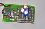
A Picaxe RGB self contained controller.
The original ”Pulsout” ideas, proposed by Hippy and Tom2000,
come from these threads:
http://www.picaxeforum.co.uk/showthread.php?t=8991
http://www.picaxeforum.co.uk/showthread.php?t=9657&page=2
My apologies if I've missed any others.
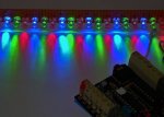
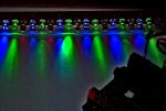
A cheap (£2 GB) Picaxe can control
A c/c RGB LED / Three separate LED's /High power or banks of LED's.
See basic circuit diagram.
Resistor values must be found by experiment or calculation.
For safety, start with 1000 ohms, then reduce the value, while measuring LED current.
Valid output pins.
08M 0,1,2,4
18X / 20M / 28X1 / 40X1 0...8
Prog 1. Cycles through values. Could be “prettied” to the nth degree.
For an eight output Picaxe, adding the lines
will control two sets of RGB lights, showing two different patterns.
With suitable maths/coding it should be possible to create complementary colours
and other interesting effects.
Program 2. A wonderful Penicillium green.
A “Master” Picaxe, using Serout, can send rTime, gTime and bTime values,
allowing the “slave”to function as a “standalone” RGB controller.
A Picaxe RGB self contained controller.
The original ”Pulsout” ideas, proposed by Hippy and Tom2000,
come from these threads:
http://www.picaxeforum.co.uk/showthread.php?t=8991
http://www.picaxeforum.co.uk/showthread.php?t=9657&page=2
My apologies if I've missed any others.
A cheap (£2 GB) Picaxe can control
A c/c RGB LED / Three separate LED's /High power or banks of LED's.
See basic circuit diagram.
Resistor values must be found by experiment or calculation.
For safety, start with 1000 ohms, then reduce the value, while measuring LED current.
Valid output pins.
08M 0,1,2,4
18X / 20M / 28X1 / 40X1 0...8
Prog 1. Cycles through values. Could be “prettied” to the nth degree.
Code:
symbol rTime = b0
symbol gTime = b1
symbol btime = b2
symbol xtime = w2
symbol R_LED = 0
symbol G_LED = 1
symbol B_LED = 2
symbol dummy = 3  ; 4 if 08M ***

setfreq m8
 main:
 for rTime = 10 to 255 step 10
 for gTime = 0 to 255 step 10
 for bTime = 0 to 255 'step 5

 xTime = 766 - rTime - gTime - bTime
 PulsOut R_LED, rTime
 PulsOut G_LED, gTime
 PulsOut B_LED, bTime
 PulsOut DUMMY, xTime
 next
 next
 next
Code:
 PulsOut 4, bTime
 PulsOut 5, gTime
 PulsOut 6, rTime
PulsOut 7, xTimeWith suitable maths/coding it should be possible to create complementary colours
and other interesting effects.
Program 2. A wonderful Penicillium green.
Code:
symbol rTime = b0
symbol gTime = b1
symbol btime = b2
symbol xtime = w2
symbol R_LED =0
symbol G_LED =1
symbol B_LED =2
symbol dummy = 3

setfreq m8
 do

  rTime = 60
  gTime = 250
  bTime = 80

 xTime = 766 - rTime - gTime - bTime
 PulsOut R_LED, rTime
 PulsOut G_LED, gTime
 PulsOut B_LED, bTime
 PulsOut DUMMY, xTime

loopallowing the “slave”to function as a “standalone” RGB controller.
Attachments
-
 57.7 KB Views: 692
 -
 52 KB Views: 586
Last edited: