Picaxe output pin to simulate momentary switch

PersonX99

New Member
I have a EL wire inverter with is "normally" powered by two-AA batteries (3v), but works perfectly well with a 5v power source (only the wire glows slightly brighter). There is a momentary switch on the inverter to switch modes as follows:

power on: inverter OFF
press once: inverter ON - CONSTANT
press again: inverter ON - FAST STROBE
press again: inverter ON - SLOW STROBE
press again: inverter OFF
(repeat)

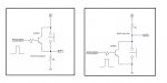
I checked the switch leads on the board and I measured 5v. I did not have a scope to see what happens when I press the button.

My question is how to use an output pin of the picaxe to 'safely' simulate the button press? A transistor switch at the output?

It's probably very simple, but I am new to the picaxe and this forum has been very helpful :)
Thanks.
 

SAborn

Senior Member
A opto coupler with its transistor wired across the switch should work, then this will keep the switch circuit and picaxe circuit seperated, also being isolated on the base it should allow for the transistor to switch either V+ or V-.
 

hippy

Ex-Staff (retired)
If you disconnect the EL driver you can probably use a meter measuring resistance to see if the switch shorts to 0V or something else.

If the EL controller input is a pull-up with switch to 0V you may be able to drive that direct from the PICAXE pin, "LOW <pin>" to activate the switch, "INPUT <pin>" to release it. If pull-down with switch to +V, then "HIGH <pin>" and "INPUT <pin>" instead. It depends on the value of pull-up or pull-down, how much current that sources or sinks from the PICAXE pin.

There are risks in doing that if you aren't confident of the EL input circuit but it's the easiest option. A transistor is next best, but an opto as suggested is probably the safer course, but perhaps not a lot of advantage over a transistor if the 0V are shared. You could also use an analogue switch.

It really depends on the EL input circuit. I'd guess it is a simple pull-up/pull-down / +V/0V but you never can be certain without reverse engineering the circuit.
 

Goeytex

Senior Member
If the circuit is either a simple pullup or pulldown then I'd suggest using a transistor across the switch. An opto can be substituted for the transistor but is not necessary. Use the Pulseout command to activate the switch.

See the attached examples.
 

Attachments

PersonX99

New Member
Thanks for all the responses. You guys helping us newbies out make tinkering with these microcontrollers a lot more FUN. I'm looking forward to trying this out tonight. I'll post my results in case someone else has a similar question.
 
Top