PICAXE handling GPS for robot boat

Technical

Technical Support
Staff member
See
http://www.picaxe.com/docs/axe024.pdf

You are not using i/o 4 yet, so connect a switch between V+ and the i/o pin on the spare servo header.
On the colour sensor holes on the PCB (see bottom of page 1 of the datasheet) solder a 10k pull-down resistor between the holes '4' and '0V'

Then it is simply 'if pin4 =1 then'...
 

Robin Lovelock

Senior Member
Brilliant Technical - that's exactly what I needed to know.
I'll check it out now with a spare board. Many Thanks.
Robin

See
http://www.picaxe.com/docs/axe024.pdf

You are not using i/o 4 yet, so connect a switch between V+ and the i/o pin on the spare servo header.
On the colour sensor holes on the PCB (see bottom of page 1 of the datasheet) solder a 10k pull-down resistor between the holes '4' and '0V'

Then it is simply 'if pin4 =1 then'...
p.s. I've tested on the spare board and it works ! Not yet tested with GPS as well, but I see no reason why that should be a problem.
IS THERE ONE MORE PIN ANYWHERE I COULD USE ? :)
If so, that opens up more options on how I can exploit this. e.g. detect sail boom swung to left or right.
But, even if we are now at the limit of input pins, this is going to be really useful: many thanks Technical.
Robin
www.gpss.co.uk/autop.htm
 
Last edited:

Technical

Technical Support
Staff member
You can hook up two (or more switches) to the same input by using it as an analogue input (e.g by each switch shorting out a different resistor in a resistor ladder). That way you can detect several microswitches on the same input pin.
 

Robin Lovelock

Senior Member
Thanks Technical: it gets better and better ! It looks as if I could try a potentiometer, driven by a wind vane, to detect the direction of wind. Would obviously need to be suitably weatherproof and robust - but my next step is to get a suitable value pot. 10k maybe ? Have just looked at the interfacing manual, and section about a pot. but did not see reccomended resistance.

It looks as if I'd just connect the pin to the sliding arm of the pot and either end to +5v and ov.
Then use READADC 4,b1 to read the pot position into b1.

I guess there are no limitations or side effects when mixing READADC with my existing SERIN and SERVO commands ?
Unless I get other advice, I'll try with a 10k pot.
 

Svejk

Senior Member
When you choose the pot remember the tear and wear: a carbon film pot will wear fast under continous movement from a wind wane. A wire wound may be more suitable for this kind of application.
 
Last edited:

Robin Lovelock

Senior Member
Many Thanks Folks. I'm off to Maplins to pick up some bits, and will also get one or two 10k pots to check
the software - I may put one up on a pole for 24/7 tests, as I have already for the power train. I'm particularly pleased today,
because I just got a (nother) suitable ND-100S GPS and manaaged to switch off static nav - it's the best accuracy I've seen
in my dabbling with GPS since 1991 and cost only 17.5 GBP on ebay, delivered the next day.
Sorry to go off-topic :)
Robin
www.gpss.co.uk/autop.htm
 

srnet

Senior Member
I would be very surprised indeed if a pot would survive several weeks\months of continuous use like that.

Its for such applications that rotary shaft encdoders were invented.
 

John West

Senior Member
I second sernet's comment. I strongly advise against using any pots in your application. Other devices are readily available for the task that are reasonably inexpensive and are designed to work in such an environment.
 

MPep

Senior Member
Long life pots are available but very expensive. The standard types available over the counter generally don't last too long.
Having said that, rudder angle indicators do contain pots. In deep-sea vessels they tend to use synchros (but only use 2 phases as the rudder does not go over 120 degrees).

I would also tend to go the magnet/hall effect method. You don't really need the accuracy but only the indication of where the boom is.
 

Robin Lovelock

Senior Member
Thanks Folks. Lots done today, including another test on Bray Lake - water still getting into boat 6, but luckily not into the autopilot bits.

Later in afternoon I was able to try yet another picaxe board with a pot and the new GPS.

The pot was obviously only for software testing - proved it was very easy - within a few minutes I was twiddling the pot to move a servo. So - as you remind me - it's now worth looking at a suitable sea-going solution. For that, I'll talk to the guys on the robot boat forum, who have been playing with hall effect devices.

I also started to test my new USB GPS with the picaxe - but have not yet got it to work - no GPS data received. Maybe I've not wired up to the usb socket correct. I know I have the 0v and +5v pins correct, because the GPS LED does what it should. Googling USB Pin Out seems to indicate that the signal from GPS to picaxe will be on the pin nearest 0v. Maybe I got that wrong, or maybe that extra picaxe board needs to be checked again where the serial input goes. Format of the gps data seems sufficiently similar to the other GPS mice used so far.

Now time for a whiskey and TV. We just got back from our local italian restaurant :)
Robin
www.gpss.co.uk/autop.htm
 

papaof2

Senior Member
I also started to test my new USB GPS with the picaxe - but have not yet got it to work - no GPS data received. Maybe I've not wired up to the usb socket correct. I know I have the 0v and +5v pins correct, because the GPS LED does what it should. Googling USB Pin Out seems to indicate that the signal from GPS to picaxe will be on the pin nearest 0v. Maybe I got that wrong, or maybe that extra picaxe board needs to be checked again where the serial input goes. Format of the gps data seems sufficiently similar to the other GPS mice used so far.
The non-power wires of the USB cable are bi-directional, high-speed data, *not* RS232 style serial.

There is *no* PICAXE that can talk to a USB device. The Universal Serial Bus is related to RS232 serial data only in the instance that both use a serial data stream.

If you can find where the serial out of the GPS chip connects to the USB<->serial converter in the dongle, you may be able to tap it there. For some devices, there is *no* 4800/9600 serial data present on the board.

GlobalSat (and others) sell their "refurb" units at a discount (if they have any) www.globalsat.com.tw

John
 

Robin Lovelock

Senior Member
Hi John - you really spoilt my day ! :) But thanks for giving me this bad news.

I did a few tests, including after borrowing my friend's 'scope, before this reply. The 'scope did not see a signal on either of the two usb signal pins, and other expoerimental changes like SERIN using T4800_16 instead of N4800_16 gave no response. I saw that the GPS used in the three other test picaxe autopilots came with ps2 connectors.

So it looks like this great little usb gps will only be used with my laptops - as if I didn't already have enough gps around the house ! :)

What surprises me is that you can buy rs232/usb serial adapters for so very little, which implies (wrongly) to me that they were little more than the appropriate plugs wired together - without any special chip inside, or software driver in the PC - I guess I was wrong.

You giving me the bad news was painful, but you must have saved me a lot of time head-scratching.

If there IS a simple work-around - including a usb conversion chip - this could be valuable for a lot of picaxe projects.

Many Thanks John.
Robin
www.gpss.co.uk - business and family.
www.gpss.co.uk/autop.htm - robot boat page.
 

srnet

Senior Member
If there IS a simple work-around - including a usb conversion chip - this could be valuable for a lot of picaxe projects.
Think of the variety of devices that are USB, Flash disks, Keyboards, Mice, Logic Anlayzers, Scopes etc.

The electrical interface is only part of the problem, you need to talk to the USB device in a language\protocol it understands, this would require a device specific driver ........
 

Robin Lovelock

Senior Member
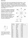
Hi Folks. I've made some progress on a wind direction sensor to plug into the spare picaxe pin. It went very quickly, and may be of interest to anyone playing around with picaxe based weather stations. For my application, detecting wind direction on the robot saailing boat, I anticipate a better solution may be some microswitches and resistors driven by the main sail boom. i.e. detecting if it is swinging loose (when boat is "in irons") or pulled against the main sheet, to one side or the other.

However, if made sufficiently accurate and robust, a true wind direction sensor might be used. This all went very quickly: just the day before yesterday (Friday) I saw a replacement wind direction sensor type WH1080 on ebay and ordered it - for just 19 GBP delivered: it arrived the very next day - and I got the system working quickly with the picaxe. The important information is in the comments of the code below. I was helped by a Forum that I found, confirming what is inside this sensor.
http://sandaysoft.com/forum/viewtopic.php?f=13&t=492&start=30
I've already posted onto the end of this thread - it helped me get a simple solution working quickly - just one 10k resistor added! :)

The only fiddly bit was working out the voltage numbers to test for - by experiment. As explained in my comments, the problem with these units is that they only include 8 reed relays, for the primary 8 directions - but for SOME positions - more than one relay closes. So the sensed voltages appear a bit random. More importantly, I suspect that behaviour may vary from one unit to the next - so the software may need to be adjusted.

I'll probably look at two things now: 1) hall effect devices to give more accurate direction 2) and/or two or more microswitches on the main sail boom.

Ideas are still welcome. Many Thanks for your input.
Robin
www.gpss.co.uk/autop.htm

Code:
 'JUST FOR TEST of wind direction sensor type WH1080 which
 'has magnet closing 8 reed relays, connected to resistors
 'but possible for more than one relay to close in some positions.
 'Needs to be calibrated against individual unit. Has four wires.
 'green wire connects to input pin 4. Yellow wire not used.
 '10k resistor between green and +5v. black wire to 0v.
 'This version translates "north" to 0, then 1,2,3 ...14 clockwise.
 'NOTE DIFFERENCES ARE EXPECTED BETWEEN INDIVIDUAL UNITS.
verytop:
 readadc 4,b1 'read from pot
 b2 = 0
 select case b1
   case > 133
     b2 = 4  '135
   case > 128
     b2 = 6  '131
   case > 124
     b2 = 5  '126
   case > 120
     b2 = 8 '122
   case > 112
     b2 = 7 '115
   case > 104
     b2 = 2  '107
   case > 100
     b2 = 3  '104
   case > 85
     b2 = 10 '88
   case > 75
     b2 = 9 '80
   case > 58
     b2 = 0  '62
   case > 50
     b2 = 1  '54
   case > 35
     b2 = 13  '42
   case > 25
     b2 = 14  '32
   case > 18
     b2 = 11 '21
   case <= 18
     b2 = 12  '17
 end select
 'if b1 <> b2 then
   'b2 = b1
   sertxd ( 10,13," ",#b1,"=",#b2, 160,10 ) 'trace output back to PC
 'endif
 'w3 = b1 * THROW / 128
 'w3 = CENTRE - THROW + w3
 'SERVOPOS 2,w3 'move servo 1 to steer boat based on GPS heading
 PAUSE 500 'wait
 goto verytop
 

John West

Senior Member
I haven't had the time to follow your project in detail, (it's a big project) so I apologize if this has been covered already, but I do suggest you apply a good conformal coating over your entire electronics bd once you are sure of your circuitry. Even if you are planning on using a waterproof housing for the electronics, a good conformal coat on the pcb itself is still a wise idea.
 

marks

Senior Member
I,m guilty of only reading the last couple posts lol
but i think those weather sensors will detect 16 positions
they all look the same i found this 1 time hope its helpful.
 

Attachments

Robin Lovelock

Senior Member
Thanks Folks. Sorry it's a few days since I checked this thread. Things have gone well, with testing of our picaxe based autopilot on Bray Lake. I've updated my robot boat page www.gpss.co.uk/autop.htm but that's mostly to update some links and add the fantastic picture of the French boat (about 1.4 metres long) braving the Atlantic waves. Latest news is that also broke (front sail) and is drifting back towards France. The only other serious attempt was by the Welsh Team a year ago - that was last seen 60 miles west of Ireland - but also broke. The rest of us, including teams around the World, are still testing their solutions.

On Bray Lake I've concentrated on testing the basic robot boat #6, without instrumentation (too heavy), programmed to steer back to the same waypoint from anywhere on the lake. We are about to try with it programmed to sail to waypoint Delta, a hundred metres out, then back to Base again. We are still working on water-proofing! :)

I've also ordered what looks like a good Hall effect direction sensor chip from Switzerland: the Ametes 360-ASMC-01. It seems to have two outputs: analogue - that we can use directly, and PWM (Pulse Width Modulation) - not difficult to measure with a loop taking maybe 1000 samples on the input pin. This sampling method may drift less in accuracy with temperature and supply voltage (between 3v and 5.5v depending on sunshine). I've ordered two chips, and hope to be testing soon. When we have a wind direction sensor on the boat, I can modify the picaxe software, and the boat may then be ready to try the total Bray Lake course, including tacking into wind - as did boat #5.

Boat #6 is only 3 ft long (less than a metre) and we've not found it big enough for the extra weight of test bits (seen on my robot boat page) so we have cut it down to the basic boat - more similar to how it might be used. However, next sail, it will probably carry a little GPS logger, for later analysis of how well it steered to waypoint D and back.

It has occured to me - but not TOO seriously - if it might be easy to make a second PICAXE test module - that talks to shore, as does our iPAQ based solution. On the iPAQ (seen and heard in the "Snoopy Sails!" video) the software speaks things like distance and direction to waypoint, and the sound is passed to an FM transmitter (similar to as used in a car to link ipod to car radio) to carry the speech to a tranny radio with us on the shore. It's also good to hear things like speed.

The picaxe autop1.bas application already sends info as text to the jack plug connected to the PC during use of the picaxe editor. How about if this serial output went to a second picaxe system, with text to speech (which I saw somewhere is available) to pass sound to the FM transmitter ?

I've got plenty to get on with for now, but any ideas on this might make me take a closer look.

Thanks for your good suggestions in the past - they often save me time.
Robin
www.gpss.co.uk
 
Last edited:

manuka

Senior Member
..and the sound is passed to an FM transmitter (similar to as used in a car to link ipod to car radio) to carry the speech to a tranny radio with us on the shore.
Robin - these little in car darlings,which sell for as low as ~US$10-$15 here in NZ,certainly have appeal, & their inbuilt features (digital Tx setting/USB/3.5mm.SD card etc) astound for the price. However regulations deliberately limit them to very restricted range, with most maxing out at 5-10 metres. Some back seat pasengers are further away than that ! All manner of (illegal) hacking has predictably arisen...

Bravo on the lakeside trials ! However,in light of the "lost at sea" accounts you relate,it's -sigh- again suggested that an extremely rugged boat may be the most crucial design need. A LONG time back in this theme I mentioned a similar & much hyped quest here in NZ (with ~£10k invested in it) that saw the 4 metre long mega robust solar powered vessel "SRV Goodwill" totally swamped just a few km offshore...

Brisk small plane flights can be organised during a suitably favourable weather window, but the very nature of a long ocean journey precludes this. En route weather & waves,barnacle & seaweed growth,sea birds & "pirates",icebergs & sea traffic can not be predicted at launch, & marine engineering for scenarios that are WORST CASE (& BEYOND!) should dominate the design. Stan.
 
Last edited:

srnet

Senior Member
As manuka has suggested the car FM transmitters are very low power, use on a lake would give you line of sight, but I would not be very hopeful.

Far more useful would be to setup telemetry, you could get back and record, all manner of useful diagnostic information .......
 

Robin Lovelock

Senior Member
Thanks Folks - but on "sailing things" - you are preaching to the converted :) Not sure if you've played the "Snoopy Sails!" video on www.gpss.co.uk/autop.htm but in that you will see - and hear - what we've been using for ship to shore voice comms over the past year or two: PMR for more than 200 metres, but FM for majority of time, less than 200 metres. I think the majority of our testing will continue on Bray Lake - until we are ready for a trip to the seaside - probably next year.

I'll repeat the end of my last posting, since that was my main query ....

The picaxe autop1.bas application already sends info as text to the jack plug connected to the PC during use of the picaxe editor. How about if this serial output went to a second picaxe system, with text to speech (which I saw somewhere is available) to pass sound to the FM transmitter ?

I've got plenty to get on with for now, but any ideas on this might make me take a closer look.

Thanks for your good suggestions in the past - they often save me time.
Robin
www.gpss.co.uk
 

John West

Senior Member
The picaxe autop1.bas application already sends info as text to the jack plug connected to the PC during use of the picaxe editor. How about if this serial output went to a second picaxe system, with text to speech (which I saw somewhere is available) to pass sound to the FM transmitter ?

Robin
www.gpss.co.uk
That's a very interesting idea, and well worth a try. I like it! As far as I know there's no reason not to implement it if it meets your needs, beyond its added complexity and expense. It should work. After it's up and running, I may borrow it from you for one of my own projects. Of course, if you have someone involved who knows Morse code, a circuit to send the text out as CW would be simpler and cheaper.
 

srnet

Senior Member
Of course, if you have someone involved who knows Morse code, a circuit to send the text out as CW would be simpler and cheaper.
And easy enough to decode with a portable PC, feed the radio audio into the soundcard, use the appropriate software.

Whilst using morse might seem peverse, if you restrict the data to numbers, its easy enough to learn these and then copy by ear even when the signals are quite close to noise level.
 

manuka

Senior Member
I've used Morse ("CW")for over 50 years & still have a sneaking regard for it. However Morse numbers are not easy to decode without considerable training and practise. In contrast a so called "Swan Code" is a breeze for even kids & oldies to to handle. It suits LED winking or piezo sounding & uses "longs" for tens (zero is a prolonged long !) & "shorts" for units. Hence 12 = long,short,short (-/./.) and 33 = -/-/-/././.)

The technique has been particularly useful for Celsius temperatures,where of course ambient insights into the approximate values usually abound, but other numeric data could easily be winked/sounded out too.
 

Robin Lovelock

Senior Member
Thanks Folks, including ideas on using morse code. Sorry I've not visited this forum for a week or two.

Testing of the PICAXE autopilot on Bray Lake is going well - with us already having sailed 120 metres to a waypoint, to within 3 metres, then sailed back to Base, to a similar accuracy. For monitoring of this, I'm using the Pocket PC GPS speaking over FM radio, as a ship-to-shore reporting system. This GPS is quite independent of the GPS-Picaxe-rudder servo autopilot. We've also had quite a few "interesting sails", including due to water having got into the system :)

I've updated my page www.gpss.co.uk/autop.htm but not yet the video.

In parallel with the initial testing of autopilot on water, I've started to test chips for wind direction sensing - in case we add a wind direction sensor. The software for this is not difficult, and I'm already testing chips with the PICAXE. However, there is always the outside chance that our sailing tests indicate that we do not need to add a wind direction sensor - strange as that may seem. I've yet to progress to tests where we deliberately try to sail upwind to a waypoint - one step at a time.


I'll repeat the end of my earlierposting, since that was my main query ....

The picaxe autop1.bas application already sends info as text to the jack plug connected to the PC during use of the picaxe editor. How about if this serial output went to a second picaxe system, with text to speech (which I saw somewhere is available) to pass sound to the FM transmitter ?

I've got plenty to get on with for now, but any ideas on this might make me take a closer look.

Thanks for your good suggestions in the past - they often save me time.
Robin
www.gpss.co.uk

p.s. I've uploaded a 5 minute video, linked from www.gpss.co.uk/autop.htm - showing the launch of boat 6 yesterday Friday 7th October, and sailing out to within 5 metres - or better - of waypoint Alpha. You can hear the voice commentary over the FM radio from the Pocket PC based autopilot - but remember this was not controlling the boat - it was just used to speak information to shore, such as distance and direction to the waypoint. Things like wind direction and vane rudder setting can be ignored. Boat 6 was controlled by the simple picaxe based autopilot.
 
Last edited:

Robin Lovelock

Senior Member
Hi Folks. Nothing heard from you on current topic (my last thread) but I've just discovered the TUNE facilty, and see that I'm in luck - no big problem in getting it to work on my current PICAXE 08M servo controller.

I popped the following into my existing AUTOP1.BAS program, being used for autopilot tests:

Code:
 'The Simpsons Theme 
 tune 0, 5,($00,$04,$06,$49,$07,$04,$00,$69,$66,$66,$66,$E7 ,$6C,$66,$66,$66,$67,$2A,$2B)
and simply connected the second servo signal (not yet used) into an FM transmitter - and - what should come over the airwaves into my tranny radio ? The Simpsons tune ! :)

I did not remove the instructions which are driving this servo - not yet used on the boat - so there is a background noise. But I can easily remove these servo commands if I want to use this output (pin 2 / leg 5) for sound.

This could be a useful means of getting information to shore from the program. I just need to work out some suitable notes or tunes for particular things like turning left or right, reaching a waypoint, or maybe even the distance to a waypoint.

Oh yes, since the above posting, the picaxe autopilot has completed the Bray Lake course several times :)

Robin
www.gpss.co.uk/autop.htm
 

srnet

Senior Member
This could be a useful means of getting information to shore from the program. I just need to work out some suitable notes or tunes for particular things like turning left or right, reaching a waypoint, or maybe even the distance to a waypoint.
Morse.

R, L, F, B, 100 etc.

I have some routines that will transmit morse tones, I have been using my PICAXE Lost Model Locator as a test bed for transmitting and decoding morse.

Morse seems peverse, but you can read it easy enough (if its slow) by ear or hook the audio output of a radio into a PC and display it on screen. I have used a netbook with a 'USB Soundscard' (99p delivered off eBay!) to display the decoded morse output on screen.
 

mrburnette

Senior Member
I've used Morse ("CW")for over 50 years & still have a sneaking regard for it. However Morse numbers are not easy to decode without considerable training and practise. ...
The generation of Morse Code is fairly efficient. I have a blog post on using Magic Morse numbers to do the conversion to 5 byte variables... Simulator code is provided. I only implemented A-Z in the demo but numbers are trivial, there is a listing showing the Magic Morse value of the digits, too.

http://www.picaxeforum.co.uk/entry.php?30-Notes-behind-Magic-Morse

I also have a routine that will demodulate and decode Morse Code... a bit more complex but easily implemented on a 08M2 with program space to spare:
http://www.picaxeforum.co.uk/showthread.php?19123-Morse-Code-Decoding-8WPM-with-a-PICAXE-08M2 There is lots of fluff dealing with the tone demodulation, the actual MM algorithm is extremely easy to implement.

- Ray
 
Last edited:

Robin Lovelock

Senior Member
Thanks Srnet. This morning it was a quick job to finish the changes - for now - and test the GPS-picaxe-servo+sound system by walking between the two test waypoints in our cul-de-sac. I carry all the bits on a little wooden tray, with a small loudspeaker in addition to the FM transmitter - all to amuse the neighbours :)

Maybe morse could be used if a HAM works out a suitable long range comms solution for me, but for now, this is just for testing on Bray Lake, when the boat will be no further than 200 metres from me.

I have even included output of distance to next waypoint/destination: I do this by a rapid number of beeps, corresponding to the number of 5 metre increments. i.e. 10 beeps if 50 metres, 3 beeps if 15 metres, etc. It's a very crude calculation of range based on differences of latitude and longitude because I don't have a SQRT. But it's good enough. The nice thing is that this is from the GPS steering the boat, rather than that in the Pocket PC which talks to shore.

In addition to range, I have two tones for turning left (low note) and right (higher note). The duration corresponds to the error angle of direction to destination. When the boat arrives at a waypoint - a 30metrex30metre box in lat/lon - it plays the theme from "Close Encounters" - which seems appropriate :)

I'm putting the extra bits (small loudspeaker and second FM transmitter) into the boat, on a different frequency - so both sound channels are available. Maybe on two tranny radios or changing my car radio channel when I'm sheltering from the rain :)

This stuff will get used on my next test sail, early next week - if the weather is kind. The steering logic has been tweaked, to try and get a smoother course sailed between waypoints, and faster completion than earlier attempts.

Robin
www.gpss.co.uk/autop.htm
 

srnet

Senior Member
If the actual distance to waypoint is not an issue, put out a tone that rises in frequency as you get closer, very easy to tell then if your moving in the right direction .....
 

Robin Lovelock

Senior Member
Thanks SRnet. We've had several test sails since I last spoke, and I'm very happy with the patterns of tone described above. Oh yes - it was not difficult to put in a SQRT to the accuracy needed - a simple iteration. Today I removed some silly bugs from my AUTOP1.BAS software which have been there for ages, including when it successfuly steered through waypoints and back to our base. They were silly things, like my not realising how primitive picaxe arithmetic is. e.g. that w3 = 180 + w3 is NOT the same as w3 = w3 + 180 :) Several other silly mistakes, which meant, for some approaches to the waypoint, the target heading - and therefor the steering - was wrong. That certainly explained some "wobbles and deviations" that I'd put down to balance of the boat. So I'm looking forward to the next sail ! :)
Robin
www.gpss.co.uk/autop.htm
 

Armp

Senior Member
A simple approximation to 'square root of sum of squares'

Given two sides A and B where A>=B then

D = A ( 1 + 0.42*(B/A)2 ) is accurate to about <1%.

I can probably dig out a more accurate approximation if needed

Found it...

D = A ( 0.995 + 0.068*(B/A) + 0.365*(B/A)2 ) is accurate to <0.3%.
 
Last edited:

Robin Lovelock

Senior Member
Thanks Folks. Sorry for this late reply. I'll repeat my last posting here, since it is still valid. e.g. I have an adequate SQRT thanks.

I just saw SRNet asked "What is it then ? " in reply to my "w3 = 180 + w3 is NOT the same as w3 = w3 + 180".

I must admit I've not tested my "wrong" statements like this - maybe I've got it wrong, but I THINK, if I used "w3 = 180 + w3" then I'd probably always get 360, because the picaxe software evaluates, as it reads. i.e. first "w3 = 180" then "w3 = w3 + w3" --> 360. Similarly, lots of other expressions might no give the result you would get with less primitive software. But "primitive" is OK if it works - and is predictable and reliable :)

Earlier post by Robin:

Thanks SRnet. We've had several test sails since I last spoke, and I'm very happy with the patterns of tone described above. Oh yes - it was not difficult to put in a SQRT to the accuracy needed - a simple iteration. Today I removed some silly bugs from my AUTOP1.BAS software which have been there for ages, including when it successfuly steered through waypoints and back to our base. They were silly things, like my not realising how primitive picaxe arithmetic is. e.g. that w3 = 180 + w3 is NOT the same as w3 = w3 + 180 :) Several other silly mistakes, which meant, for some approaches to the waypoint, the target heading - and therefor the steering - was wrong. That certainly explained some "wobbles and deviations" that I'd put down to balance of the boat. So I'm looking forward to the next sail ! :)
Robin
www.gpss.co.uk/autop.htm
 

MartinM57

Moderator
I THINK, if I used "w3 = 180 + w3" then I'd probably always get 360, because the picaxe software evaluates, as it reads. i.e. first "w3 = 180" then "w3 = w3 + w3" --> 360. Similarly, lots of other expressions might no give the result you would get with less primitive software. But "primitive" is OK if it works - and is predictable and reliable :)
......
...They were silly things, like my not realising how primitive picaxe arithmetic is. e.g. that w3 = 180 + w3 is NOT the same as w3 = w3 + 180
Please rest assured that w3 = w3 + 180 and w3 = 180 + w3 have exactly the same result...if they didn't ... well ... we'd all be in a complete mess ...
 
Top