Picaxe clock regulation

Rampz

Well-known member
I can't see it's any different to removing the weights and replacing them with a coil spring and a motor...
Phil, i found today that in the 1960's Smiths did away with almost everything except the hands and fited a AC motor and chain drive and controlled that from a control box, Seems under conservation thats not allowed any more.

The feeling is with the weights removed and left in the bell tower they can be reused in the future if required, removing the pendulem maybe going too far on a turret clock, alot better on a smaller clcok with lesser forces involved
 

PhilHornby

Senior Member
The feeling is with the weights removed and left in the bell tower they can be reused in the future if required
It's never gonna happen :)

I came across an interesting 'auto-tuner' using an Ar*u*no, here: http://www.servoelectricguitar.com/clocktuner.php
What makes it interesting, is that you can (theoretically) remove the power, once it's done its thing - and the pendulum stays regulated...

This led me to a design for an 'auto-winder' for a chain-driven, Grandfather clock like mine. Now I like the ritual of winding the clock, so I'm not in the market for one of those - but I thought the engineering was fantastic: https://bhi.co.uk/wp-content/uploads/2021/09/June-HJ-2021-AOTM-1.pdf
 
Last edited:

Rampz

Well-known member
This led me to a design for an 'auto-winder' for a chain-driven, Grandfather clock like mine. Now I like the ritual of winding the clock, so I'm not in the market for one of those - but I thought the engineering was fantastic: https://bhi.co.uk/wp-content/uploads/2021/09/June-HJ-2021-AOTM-1.pdf
Phil this used to be used in the 1970s it was dubbed monkey-up-a-rope and was a motor and gearbox that climbed the same as the article describes.


came across an interesting 'auto-tuner' using an Ar*u*no, here: http://www.servoelectricguitar.com/clocktuner.php
What makes it interesting, is that you can (theoretically) remove the power, once it's done its thing - and the pendulum stays regulated..
Very interesting idea a great read.
 

Rampz

Well-known member
Ok as an update i have spoken to the manufacturer and he wants to keep the minimum amount of interaction with the user and the existing clock when it comes to fitting the regulation, there will sensors to attached and a magnet to cable tie to the pendulem but beyond that he doesn't want the self installer to touch anything else, what the self installer has to do can be covered in the fitting instructions, when a church approaches the subject of regulation there is a whole list i questions that are asked at the start of the process, like length of pendulem etc, i haven't seen the list
 

Rampz

Well-known member
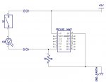
Regards position sensors to detect the position of the pendulem and strike mech currently they use a reed switch with a led in a tiny housing and its a 2 wire unit, which in can't see working with PICaxe, i can't see that i can draw any current from an input? I don't really want to use and input and an output per sensor, maybe i can connect the reed in series with the led and between a picaxe pin and 5v with a smaller pullup resistor so the led will work?
Any thoughts on how to do this, it seems best to have the indicator built-in with the reed switch, i can go 3 wire if need be i guess?
 

Rampz

Well-known member
Something along these lines?
Yes Phil that was what i had in mind but wasn't sure how the picaxe would respond to a 1k rather than the normal 10k requirement, i find 1k resistor on a led is fine when using one on an output pin
 

Rampz

Well-known member
So after about a year of playing about with the idea, Jack Burns has been helping me with the coding, no not quite like that until now is has done everything needed to get the code to work along the lines of Hippy's finite machine setup, we have had to go from a 4 bit screen to a 8 bit screen due to the amount of program space 4 bit was using, that mean't we needed more pins and we ended up using the 40X2 smd.
A recent issue was with the inductive sensor i have used, i looked all over and thought i had found a sensor that would work on 5V, turns out they don't work very well on 5v, work fine on 6v, so had to run them from battery volatge 11.4 to 14.4v and connect it via a PC817 optocoupler and it works well now.
I have designed and built the pcb, that's about as useful as i have been.
I will add the circuit diagram shortly.
Jack has done a great job and there is loads of info in the attached .BAS file.
My job coding wise is to get the pendulum catcher to work
 

Attachments

Last edited:

hippy

Technical Support
Staff member
Jack has done a great job and there is loads of info in the attached .BAS file.
So does that mean it's all working now ?

Congratulations if it is, well done for persevering and getting there. I'll be taking a look at the code later.

FYI : Your second post seems to have the PCB file twice, rather than PCB plus schematic.
 

Rampz

Well-known member
So does that mean it's all working now ?

Congratulations if it is, well done for persevering and getting there. I'll be taking a look at the code later.

FYI : Your second post seems to have the PCB file twice, rather than PCB plus schematic.
Yes my mistake i have corrected it now.

The code works very well but at the moment the catcher doesn't catch the pendulum as i have to sort the code for that to happen, Jack tells me when the clock stops in the code it restarts at the correct time, which is great, we don't have much code space left for the catching code that i need to work on, I'm still waiting for the clock bloke to get the chime side of my clock working so i can leave it running etc
 
Top