Picaxe battery charger issues.

sniper887

Member
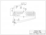
I have attempted to build a battery charger for AA size NiMH batteries and have been running into an issue. With the current setup if I connect a battery the Picaxe repeatedly resets, unless I add a 10 or 15 ohm resistor in series, then it works properly. I'm thinking when the MOSFET turns on it pulls enough current for an instant to cause the voltage to collapse. I have removed the capacitor across the battery terminals and still the same issue. Any way to get around this while still being able to supply 1A or so of charge current? With a 10 or 15 ohm resistor I can't get over about 200 milliamps to the battery because of ohm's law. I've been pondering running a regulator (3.3 volts perhaps) but if the supply voltage collapses that may not do any good. Another idea is a buck topology (rearranged to allow low-side switching) but that would require large inductors (on the order of 330 uH) if the Picaxe drove it directly. For the record this basic circuit worked on my AXE091.

14m2 charger.jpg
 

srnet

Senior Member
So when you connect the battery, and the power supply has to deliver 1A (of charge current) the PICAXE resets ?
 

sniper887

Member
Since it's PWM it might actually be a pulse of more than that. The code starts with a battery detection loop where the PWM is turned on at a low duty cycle, the circuit detects the small current when a battery is connected, then continues to the main charging loop. At the moment it can't even get past this phase without the series resistor.
 

srnet

Senior Member
So maybe put an oscilloscope on the supply, connect the battery and see what happens to the supply voltage ?
 

Goeytex

Senior Member
There is no series resistor between the Picaxe I/O pin and the gate of the MOSFET. This means that the Picaxe I/O pin will try to source & sink about a one amp current spike each time the FET is turned off or on. This could be the cause of the resetting. There needs to be a resistor here. A value of 330R to 1K should be ok.
 

rq3

Senior Member
Couple of things right off the bat. The 22K resistor R3 on the SERIN line is on the wrong side of the 10K resistor. LED D1 will prevent the SEROUT line from ever going much higher than the forward voltage of the LED (may or may not be an issue, R5 dependent).

Why is Picaxe Pin 12 connected to +5? Is there something in the code that needs it?

I assume the battery goes across J1, Pins 1 and 2? What is the function of C3? The battery is effectively a much larger cap than C3 will ever be (unless it's a multi-Farad supercap)!

I'm also assuming that the battery you're charging is NOT the battery running the Picaxe supply!

How big is C1? A low impedance tantalum electrolytic of at least 100 uF might help a lot there.
 

rq3

Senior Member
There is no series resistor between the Picaxe I/O pin and the gate of the MOSFET. This means that the Picaxe I/O pin will try to source & sink about a one amp current spike each time the FET is turned off or on. This could be the cause of the resetting. There needs to be a resistor here. A value of 330R to 1K should be ok.
@Gooeytex. Good catch! Also, darned if I can find a datasheet on the A03414. Comes up with a weird Sanyo FS number.
 

sniper887

Member
The series resistor for the MOSFET gate will be addressed. About the programming circuit, I'll have to fix that. Shocking that it still works! Picaxe Pin 12 may or may not be necessary. I have it to read the actual supply voltage, and subtract from that the ADC value for the battery negative terminal to get the battery voltage. Since the supply voltage is the +Vref that actually means it's not necessary. C3 has been removed from the circuit. For power I'm using a 5V 1.5A wall wart. C1 is a 1000 uF electrolytic. The bypass cap is a .1 uf. I looked at the power on my oscilloscope and it looks like ringing. Strange.
 

sniper887

Member
Doing some more testing I figured out that if the MOSFET is just on (not pwm) and I hook the battery up the circuit keeps going and draws 2 amps. It seems to have a problem with the PWM specifically.
 

sniper887

Member
I'll need to etch a new circuit board to add the resistor. Sounds like that may fix the issue. I'll let you know how it goes.
 

Goeytex

Senior Member
Etching a new board should not be necessary. Just cut the trace and solder the resistor across the cut. I would suggest starting with a 330R resistor to get the best drive possible from a Picaxe I/0 pin.

As a general practice. boards should not be etched /ordered. etc before extensive breadboard or protoboard testing. In other words. make sure it works before making boards. From looking at your schematic you may need to make some some other changes as well.

I am not sure what the feedback from the current sense resistor is for, but I suspect that some modifications/ component additions will be needed there as well.
 
Last edited:

sniper887

Member
The board was messed up to begin with. I tested thoroughly with the AXE091 and it worked. I guess moving it to a PC board raised some issues that you guys pointed out. What do you recommend with the current sense resistor? In the code I take several readings from that and average them and get accurate current control.
 

Goeytex

Senior Member
In the code I take several readings from that and average them and get accurate current control.
I can't imagine how it could be accurate, since it is a low level pulsed DC (PWM) and not an integrated signal. It is generally not a very good idea to used pulsed DC for ADC readings. Who designed the circuit?

We need to see your code.
 

sniper887

Member
Here is the code:


Code:
batdetect:
toggle b.0
pwmout b.2, 255, 50
gosub current


if w3 > 1 then init


pause 2000


goto batdetect


init:
pause 2000


symbol peak = w1
symbol actual = w0
b27 = 0
b24 = 0
peak = 0
actual = 0
pwmout b.2, 255, w10

w10 = 0
start:


for w11 = 1 to 50
toggle b.0


gosub current

if w3 < 80 then
w10 = w10 + 1 max 1023
endif

if w3 > 80 then
w10 = w10 - 1 min 0
endif


gosub transmit
pwmduty b.2, w10

next w11

pause 2000
pwmduty b.2, 0
gosub voltage

gosub transmit


b14 = w1 - w0
if w6 > 12500 then
if b14 > 1 then 

inc b24

endif
endif
if b24 > 3 then endchg


goto start


current:

if pinc.3 = 1 then init
fvrsetup FVR2048 ; set FVR as 2.048V
adcconfig %011 ; set FVR as ADC Vref+, 0V Vref-
		
		
for b26 = 0 to 99

readadc b.3, w4

w3 = w4 + w3

next b26

w3 = w3 / 100

return

voltage:
for b4 = 0 to 19
fvrsetup off ; disable FVR 
adcconfig %000 ; set FVR as ADC +5V, 0V Vref-


readadc10 b.4, w8
 
w0 = 1023 - w8
w5 = w0 + w5
next b4
w0 = w5 / 20


if w0 > w1 then
b24 = 0
 w1 = w0
endif


debug
return

endchg:
pause 5000

endchg1:

pwmduty b.2, 1000
pause 100
pwmduty b.2, 0
;if pinc.3 = 1 then init

w8 = 0
w9 = 0
w5 = 0
actual = 0

peak = 0
gosub voltage

if w0 > 900 then batdetect
pwmduty b.2, 0
pause 5000

goto endchg1


transmit:

w6 = w0 * 49

w5 = w11 // 12
if w5 = 0 then
sertxd (#w3,"  ",#w6)
endif


return
 

Attachments

sniper887

Member
Update: I made the new board with the resistor in series with the gate (390 ohm that I had laying around). Still didn't work. Then I just decided to insert a diode across the battery terminals reverse biased like a freewheeling diode. Now it works. I have no idea why.
 

sniper887

Member
As for the current sense resistor, if you see the code you see that I read the ADC value 100 times then average the results. Basically integrating the signal in the software. Since this code doesn't have to run fast this works for me. If you don't want the extra software overhead with this, then using an RC filter or some other hardware means to integrate the signal is necessary.
 
Top