PICAXE as a quiet hobby

PhoenixRider

New Member
I have been playing around with a 40x1 Pickaxe and a LCD screen and a servo-mounted Sharp IR distance sensor and an IR Beacon detector and with Hippy's excellent Pickaxe <=> PC serial comms program and Visual Basic I have it all displaying on a radar-like display and in general, keeping myself quite well entertained (and my wife quite impressed).

With the help of this forum, that is. A lot of help. I was convinced I had fried my first Pickaxe! How embarrassing. Order another chip WITH resonator this time. Turns out the 28x1 DOES need the resonator. The chip WORKS! I feel better. Now what do I do with a spare chip - hey I2C - and I got that EEPROM ... and I NEED some of those HopeRF units. If only those guys would finish up the research & testing and help a couple of newbies through the process ...

Each step of the way I was thankful I could search this forum. I am so impressed with the level of expertise and general helpfulness exibited by so many. OK, gush over. Because now I have to step out and ask:

What are the factors that affect the noise level of motors, gearboxes and servos? And anything else I missed?

I purchased a small cheap Tamiya robot kit intending to mount the IR systems and take the show on the road but it was quite slow & noisy. I spent a bit more for a better kit from OWL but it was only marginally better.

My wife has been very ill for several years and has become extremely sensitive to any noise and while she really does enjoy my hobby (well, as much as any wife enjoys her husband's hobby), she really cannot stand that much noise.

Rather than keep trying I thought I would ask the overnight global brain trust :)

And Hippy, it would seem to me that I am not the first to want to display polar coordinate data in VB. Seems like a waste to convert to pixels or twips or pips and process it that way. Then when I want to rotate the data because the robot turned it is really complicated in screen coordinates when it would be so simple in polar coordinates. I would like to think that someone smarter than me has already addressed this issue and I just don't know enough to phrase the search. Maybe an object with an internal polar coordinate convention?

Thanks
 

marcos.placona

Senior Member
Hi PhoenixRider, it's interesting to see that in a short period of time you were able to do so much. That does prove that picaxe's are the best when talking about the learning curve.

Well, back to your problem, the noise we talk about here is normally the back emf noise which will cause problems on the output line.

It's not exactly related to the noise generated by your gearboxes (AFAIK, someone correct me if I'm wrong), but by the motors itself and it's electrical noise.

A way to suppress this kind of noise would be by using a 220Nf non-polarized capacitor across the connectors (as shown on manual 3), or go for the brushless motors, which promise to generate much less noise.

Well, I'm sure someone here will come up to complete my answer, and make it even better, but those are my 2 cents
 

manuka

Senior Member
Alas- I fear the noise is not the easily tamed (~100 nF) ELECTRICAL type, but instead is ACOUSTIC sourced. Can the poster please elaborate !

HopeRF goodies pretty well nailed down- see 433MHz posting. Stan in NZ
 

marcos.placona

Senior Member
We're talking about two different things here aren't we?

There's the acoustic type (not much can be done I'm afraid, but you can change the motor / gearbox)

And the electrical type which can be fixed, but won't interfere in anything in regards to the acoustic type
 

Dippy

Moderator
"What are the factors that affect the noise level of motors, gearboxes and servos?"
- type & quality I would imagine are big contributors. I don't know these kits but I assume they are cheap'n'cheerful?

Open or enclosed gearboxes, quality, motor bearings, motor brushes etc (I assume it's not a high quality Maxon or Leeson motor?), dry cogs vs oiled cogs etc. Basic mechanical issues... oh and the quality of your construction?

You'll never make it silent but can you enclose it?
 

marcos.placona

Senior Member
"You'll never make it silent but can you enclose it?"

I thought about this suggestion too, but wouldn't it bring another problem? I mean, if you enclose it, you have to be aware of the motor's temperature right?
 

PhoenixRider

New Member
Thanks for the quick response. No, licked any electrical noise problem thanks to the many patient explanations I found here.

I am talking about acoustic noise and while that is not a Pickaxe problem, what I have nocticed about this forum is the variety of interests/skill sets that all congregate here around this micro. I am hoping that some will be familiar with and could make characterizations of drive system components.

And yes, I am very excited about the capabilities of the Pickaxe. I was an Instrument & Controls tech at solar power plant and although I am no longer working with turbines, generators and boilers I find the instrumentation in robotics to be just as much fun. And I have been reading the past posts and realizing this little chip gives me most of the same capabilities as $50,000,000 DCS systems. OK, granted it would take truckloads of Pickaxes and support chips. But these run rings around our traditional SCADA and ladder-logic and PID controllers. I do not mean the Pickaxe is a replacement for any of the more robust methods. Rather I rejoice that I can have for $ what so recently cost thousands plus the associated thousands or $100k's and usually specialized training.
 

nzdragme

New Member
I had a similar issue...

Now I'm banished from the house. And apparently the vacuum cleaner doesn't suck up the clipped ends of soldered components either :rolleyes:
 

PhoenixRider

New Member
exactly the type of information I am looking for. I would assume that cheaper is louder. But metal vs plastic gears? Running higher capacity motor slower? Or smaller motor faster? Gearhead vs??? I can come up with a lot of possibilites but have little opportunity to test.
 

hippy

Ex-Staff (retired)
On handling polar coordinates - I'd keep using polar coordinates so you can do easy transformations and rotations in software and only convert when you come to display something. It means you have to convert every time but does make it easier. I don't know of any handy VB Objects to use; a Google search including ActiveX or OCX may turn up some display handlers which can take in polar coordinates, X-Y references and draw what you want.
 

manuka

Senior Member
Methinks you'll either have to settle for very quiet PICAXE ( note - no "K") projects, or put up a wee shed down in the garden. Endless men have chosen the latter of course, c/w facilities in keeping with the needs of mid life male ( large screen LCD, beer fridge etc).

Thanks for the comments about PICAXEs - I hope Rev.Ed are reading ! Stan
 

Rickharris

Senior Member
Almost all gear box's benifit from adding some grease even plastic gears.

If all else fails go to pullies and rubber bands or O rings as belts - almost silent.

At the extreme end of construction pizeo motors, plantary gear boxes, friction drives are also very quiet. OR sound absorbant material round your wifes room! Noise cancelling earphones can be obtained and will deaden aircraft engine noise.
 

BCJKiwi

Senior Member
A lot of the noise which annoys is amplified/transmitted from its source by the structure and mounting methods.

1. Try to reduce the noise (and vibration) at the source.
Plastic gears, non-straight cut gears, belts instead of gears, grease on gears will help with the source.

2. Mass and rigid construction help with transmission as does enclosure/damping/insulation.
Heavy gauge chassis, flexible mounting to that chassis, even plastics in the chassis instead of metal.

Note that enclosure does not necessarily mean a closed box.

Ever wonder why there is that bitumen like coating sprayed on the underside of the car bonnet in some models? That's to damp the vibration, not to stop rust. So sound dampening coatings/insulation on covers will help even if not total enclosures.

A few things to ponder and to experiment with.
 

gidgee

Member
Almost all gear box's benifit from adding some grease even plastic gears.

Try Graphite flakes as a lubricant, magic stuff
john
 

premelec

Senior Member
I don't know how big the machine is but I still have large open cell foam lined box which was used to keep a dot matrix printer from driving everyone nuts who was near it... probably 30 db noise suppression but I never measured - has hinged lid and
acrylic view panel... think small foam lined trunk with wild robot inside!
 

hax

New Member
Just some more thoughts from experience:

I made a curtain motor controller and the first version used a small electric screwdriver for the motor source.

The small motor had a high RPM and had a lot of gears to increase torque. It was very loud and did not sound very elegant at all.

I swapped it over for a windscreen wiper motor. This was a larger motor with only one gear but because the RPM was much lower, there was much less noise.

What we perceive as loud is in the higher frequencies, so a high RPM will generally sound louder to us than a lower 1khz or less sound. That's why smoke detectors sound very loud and they only have a small 9V battery to power the siren, while you need hundreds of watts to make a bass sound nearly as annoying.

If you can't change the motor in your application, maybe you can change the gear ratio and use PWM to attempt to keep the torque and speed that you had....
 

D n T

Senior Member
My wife doesn't like noise but she likes my&quot; cheap &quot; hobby&quot;

I had the noise problem and my wife reckons I need to quieten down, she works nights, and thats when I start "chipping away", but problems arise when I start chipping away on the weekend when she is asleep.

I sorted this out by using R/C servos and "hacking" them ( cut the tab, bypass the POT and solder in a voltage bridge, easy, even for me), they are quiet ( quieter) tonnes of torque and they are easy to mount and they don't go too fast.
They are easier to wrap foam to quieten them down.

By the way "she who must be obeyed" also likes the fact that PICAXE is not as expensive as car racing or doing up cars, although I'm sure I could make it as expensive if I try!!!
 

Tom2000

Senior Member
And Hippy, it would seem to me that I am not the first to want to display polar coordinate data in VB. Seems like a waste to convert to pixels or twips or pips and process it that way. Then when I want to rotate the data because the robot turned it is really complicated in screen coordinates when it would be so simple in polar coordinates. I would like to think that someone smarter than me has already addressed this issue and I just don't know enough to phrase the search. Maybe an object with an internal polar coordinate convention?
You don't need any special code to convert from polar to rectangular coordinates. Just a teeny, tiny l'il bit of trig.

I'm guessing that your sensor system returns values to you in the form of distance from your sensor, and the angle that the sensor is pointing at the moment.

In other words, your data consists of radius and angle.

You want to display its equivalent on the screen, so you need to convert from your radius-angle data to screen X,Y coordinates.

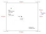
When you encounter something like this, the first thing you need to do is to set the problem up as a basic sketch. With that in mind, I brewed up a little sketch and have attached it.

I'm guessing that you want your origin right in the middle of your drawing area, and you're trying to plot the unknown point (that green thingie in the sketch.)

A few things to notice:

1. Your screen coordinates start in the top left, at 0,0. X increases as the pen moves south, and Y increases as the pen moves east.

2. Your origin is at X = Width / 2, Y = Height / 2.

3. Computer trig works with angles starting with 0 degrees due east of the origin, and increasing as you move counter-clockwise. (Note the red figures in the sketch.)

4. And although not noted on the sketch, computer trig works in radians, not degrees. That's something else to consider.

With that in mind, we can proceed.

First, you won't be making your initial calculations from your Width / 2, Height / 2 origin coordinates. You'll be using an origin having the coordinates of X=0, Y=0.

With all this in mind, let's pre-scale your data.

First convert your angle to the computer's frame of reference. You probably use due north of your sensor's position as the 0 degree point. Shift the sensor angle to the computer's frame of reference by adding 90 degrees.

If your sensor increases angle as you rotate clockwise instead of counter clockwise, you have a further correction to apply. Again, draw yourself a little sketch so you can sort it out properly.

Next convert that angle to radians. If VB has a DegToRadians function, use it. Otherwise, multiply your angle by (2 * pi) / 360.0 to get the angle in radians.

Next scale your radius so that your maximum measurement range is equal to half the drawing area's height.

Now that you have your angle and radius scaled to something the computer can understand, it's time to convert those numbers to X and Y offsets from your 0,0 coordinate reference.

Here's all you need to do:

X = Radius * cos(Angle)
Y = Radius * sin(Angle)

Somewhere in those calculations, you'll have to convert the floating point radius and angle to integer values for the X and Y coordinates. Look for something like a Round() function.

Now, all you need to do is convert the 0,0 frame of reference back to your Width/2, Height/2 frame of reference:

X = X + Width / 2
Y = Y + Height / 2

Finally, adjust your coordinates for the negative Y direction. (For example... let's say you're plotting a point due north of your sensor. The Y value returned by the above calculations will give you a number that's, say, 100 pixels above your origin. But you're actually reducing the Y value as you move north, so you have to compensate. Again, it's much easier than I'm making it sound. "Draw yourself a little sketch..." :) )

That's it. Paint your canvas and go home.

The whole process is simpler than I've made it sound. I wanted to cover every step along the way, though, to walk you through the entire process.

Hope ithis helps.

Tom
 

Attachments

Last edited:

BenjaD

New Member
Quieter motors?

Hmmm...seems that using better bearings, and belts instead of gears are the best ways to keep a motor quiet. Also, as previously mentioned, the more expensive => Better quality => quieter....usually!

Ben, South England
 

Michael 2727

Senior Member
Worm drive reduction gearboxes tend to be less noisy than
most toothed types, or like Rick H said, pulleys and rubber belts.
2¢ worth.
 

jodicalhon

New Member
A very clear and useful explanation, Tom.

Is this bit back to front?:
1. Your screen coordinates start in the top left, at 0,0. X increases as the pen moves south, and Y increases as the pen moves east.
 

Tom2000

Senior Member
A very clear and useful explanation, Tom.

Is this bit back to front?:
1. Your screen coordinates start in the top left, at 0,0. X increases as the pen moves south, and Y increases as the pen moves east.
OOPS!!!!

There's a phase shift in the wind. :)

Yes, X increases eastbound, and Y increases southbound.

And I was fuzzy about the polar to rectangular algorithm, too. Here's a clearer set of expressions:

X = Radius * cos(angle_in_radians) + X_center
Y = Y_center - Radius * sin(angle_in_radians)

Those expressions both convert polar to rectangular and change the frame of reference from the 0,0 origin to the Width/2,Height/2 origin, correcting for the negative Y axis "polarity."

Hope I didn't confuse you too much with my previous posting.

Good luck!

Tom
 

moxhamj

New Member
Re"1. Your screen coordinates start in the top left, at 0,0. X increases as the pen moves south, and Y increases as the pen moves east."

Hmm. If you make x=0, y=0 the bottom left corner, you could fix this by taking your monitor and rotating it 90 degrees counter clockwise. Or would x still not be right?

Of cuorse, some of your other software might be hard to use...
 
Last edited:

Tom2000

Senior Member
Re"1. Your screen coordinates start in the top left, at 0,0. X increases as the pen moves south, and Y increases as the pen moves east."

Hmm. If you make x=0, y=0 the bottom left corner, you could fix this by taking your monitor and rotating it 90 degrees counter clockwise. Or would x still not be right?

Of cuorse, some of your other software might be hard to use...
ROTFL !!!

Now that's thinking outside the box!
 
Top