Hi All
Thanks for looking. I have what is probably a simple problem to solve if you know what your doing, which I do not!, so I need help please. I don't want to try and solve it with trial and error as I usually would due to the costs of the micro pucks I use which are blown easily.
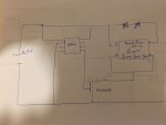
The circuit is very simple in that I use a PICAXE chip to switch on a N channel mosfet which in turn sinks a micro puck which then drives two high power LEDs in series high power LED. The problem is that the micro puck must be connected to the LED when powered otherwise they burn out. So if an LED blows or a wire is disconnected then the micropuck burns out at a significant cost. Here is a link to the micropuck documentation and I have the puck setup as in page 4, a buck/boost driver.
I was hoping to overcome this by introducing some sort of feedback circuit to the picaxe from the LED. So if the circuit is broken in anyway then the pixace will immediately switch off the mosfet and thus the micropuck will also be turned off.
I have drawn a simplified version of the circuit and my question is what should I do to safely connect the feedback channel to the picaxe. Do I need a resistor in the feedback channel and or should I have a resistor and connect the leg of the chip to ground?
The circuit is powered by a 4.2V battery and the micro puck boast the voltage to 7V and holds the current to 500mah. The pic only works at 3V-5V.
I appreciate there is probably a very simple answer to this but any help would be appreciated as my electronics knowledge is very basic.
Thanks for your help. I am sorry that the schematic is a sketch but I tried to do it in diptrace but it was harder than expected to find the symbols.
JPU
Thanks for looking. I have what is probably a simple problem to solve if you know what your doing, which I do not!, so I need help please. I don't want to try and solve it with trial and error as I usually would due to the costs of the micro pucks I use which are blown easily.
The circuit is very simple in that I use a PICAXE chip to switch on a N channel mosfet which in turn sinks a micro puck which then drives two high power LEDs in series high power LED. The problem is that the micro puck must be connected to the LED when powered otherwise they burn out. So if an LED blows or a wire is disconnected then the micropuck burns out at a significant cost. Here is a link to the micropuck documentation and I have the puck setup as in page 4, a buck/boost driver.
I was hoping to overcome this by introducing some sort of feedback circuit to the picaxe from the LED. So if the circuit is broken in anyway then the pixace will immediately switch off the mosfet and thus the micropuck will also be turned off.
I have drawn a simplified version of the circuit and my question is what should I do to safely connect the feedback channel to the picaxe. Do I need a resistor in the feedback channel and or should I have a resistor and connect the leg of the chip to ground?
The circuit is powered by a 4.2V battery and the micro puck boast the voltage to 7V and holds the current to 500mah. The pic only works at 3V-5V.
I appreciate there is probably a very simple answer to this but any help would be appreciated as my electronics knowledge is very basic.
Thanks for your help. I am sorry that the schematic is a sketch but I tried to do it in diptrace but it was harder than expected to find the symbols.
JPU
Attachments
-
 56.3 KB Views: 46