picaxe and Dinsmore compass

86atc250r

New Member
Quick question -

If I were to purchase a Dinsmore 1490 Hall Effect Digital Compass
http://www.robsonco.com/Dinsmore/Untitled_5.html


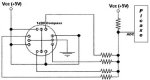
Would it be feasible to built a "network" of voltage dividers to bring the input into one ADC input of the picaxe instead of using four digital ports?

If so, have I drawn the circuit up correctly in the diagram below (bearing in mind two may be active at any one time)?
 

Attachments

Last edited:

BCJKiwi

Senior Member
Would not think so.

A separate velue off each sensor is required to work out the heading. interconnecting them as per the diagram in post 1 would effectively combine the outputs into a meaningless value with no knowledge of which of the four outputs are contributing to the Picaxe input.

There are many other compas devices avaialble using a single adc, pwm, or i2c output.

e.g. the CMPS03 used by a number of contributors to this forum - do a search.
 
Last edited:

westaust55

Moderator
Digital to Analogue using R-2R resistor ladder

If I read the article correctly, the outputs are open collector and thus either open circuit (for off state) or tied to ground through the transistor (=low for on state).

As such you would have to effectively invert/transpose the typical R-2R resistor ladder network to achieve a binary/digital to analogue signal.

For a conventional resistor ladder network, have a look at: http://en.wikipedia.org/wiki/Resistor_ladder
 

hax

New Member
The HMC6352 from Sparkfun is great.

Just uses a few i2c commands. Below is the successful code I am using on a 20x2 chip.

When the serial port sends a "PA" string the compass replies with a number from 0 to 3600

Divide this number by 10 for full degrees. Oh yeah, problem is that it is an SMD part and you would need some sort of breakout board to use it on a breadboard.


for b0 = 1 to 30
wait 1
next

disconnect

i2cslave $42, i2cslow, i2cbyte


main:
serrxd ("P"),b1
if b1 = "A" then readcompass

goto main


readcompass:
i2cwrite ($41)
pause 7
i2cread (b1,b0)

sertxd (#w0,13,10)
goto main
 

westaust55

Moderator
Compass DAC circuit

Here is a modified R-2R ladder network.

You can see that some of the possible analog output voltages are quite close.

You could try playing around with resistor values but I leave that to you.
 

Attachments

86atc250r

New Member
Thanks for the help guys,

I built the R-2R Ladder this evening and tested it (without the compass since I have yet to order it) - here are the ADC readings I got... They seem to be very repeatable. They are also almost exactly as I calculated before building the circuit, which was an added bonus.

Below are my actual readings. I used 1.5k and 3k ohm resistors for testing. Picaxe 20X2

Code:
	8bit	10bit
NE	95	383
NW	106	426
N	127	511
SE	134	536
E	153	614
SW	157	630
S	170	682
W	183	731
 
Last edited:
Top