Picaxe 28X1 getting Hot!

Michael V

Senior Member
The answer must be in the forum somewhere, but it seems i can't do a search on "Hot", not enough letters, and i don't know a longer word for hot.

I have made up a new circuit for a Picaxe 28X1. I can't download a program into it, and i know that from other projects i have that connected the input circuit and reset circuit properly, and my download cable is OK. The only output device connected so far is a LED in series with a resistor on output 7, although the circuit board already has a whole bunch of wires for input, i2C for LCD etc. Checked these with the multimeter, as best i know how.

After trying for a few minutes i noticed the Picaxe became really hot. I don't recall any of the smaller ones doing that. I can't see that there is anything on the output that would be drawing current to make it hot.The power supply is a very smooth 5.0 V.

Is this normal? Could whatever fault i have that makes it hot be the same one that is stopping me from downloading the program? If there is a short somewhere where would I look?

I would have thought there would be no current going out of the thing unless i have told pins to go high, and i haven't been able to say boo to it yet. At one stage the LED did light up, don't know why, but that would not be enough current to make it hot.
 

moxhamj

New Member
If all the circuitry is ok then it may be cooked internally with an internal short. Double check the wiring. Also maybe take out the chip and just check the power supply is correct. Chips can get zapped eg by the -12V from the programming pin. How much of a rats nest is the circuit? It may need a new chip (usually a Grrr moment).
 

hippy

Technical Support
Staff member
It definitely shouldn't be getting hot. Probably worth trying on breadboard with a minimal download circuit and a LED+R.
 

MPep

Senior Member
Sounds like you definitely have a short circuit somewhere or reverse polarity power applied.

I had an DS18B20 that I tried for the first time, and I almost burned my finger on the package. Turns out I had the power applied in reverse, +5V where 0v should go and vice versa.
Once corrected it still worked!! Amazingly enough.
 

BeanieBots

Moderator
The only way I've ever managed to get a PICAXE (08M) HOT, is with reversed power supply. Even a shorted output will only make it get warm.
They are very tough, so you may well have "got away" with whatever the fault is. Over-volt such as connection to the wrong side of a 12v->5v regulator is usually instant death though.
 

Michael V

Senior Member
Partially Blown?

Well, not sure what happened, but i can download now, and it is not cooking. I am actually using a Modtronix SBC unit with a prototype board http://www.modtronix.com.au/product_info.php?cPath=1_23&products_id=256 and have attached the programming circuit and reset connections via a prototype board. Makes attaching the I2C LCD easy. It is possible that i misconnected the daughter board, i.e misaligned the pins. I was pretty careful though.

Anyway, now i can download a program and make my LED flash. I can also write instructions to the LCD via I2C.

However, i can't make any sense from the ADC inputs. No ADC, no pulsin, no readtemp. Readtemp returns 0. I can definitely measure a voltage output from an analog sensor at the board connecting pin, but it returns a result of 0 or 255.

Is it possible to partially destroy a picaxe so that it will program, output and not input?

If i misaligned the connector, and there was 12V where there should not have been, would that explain the heat and subsequent partial destruction?

Am i phoning Microzed tomorrow? (Grrr)
 

BeanieBots

Moderator
It certainly IS possible to partially destroy a PIC chip.
The most common is a blown ouput where one of the bipolar stages has melted causing a short to either 0v or Vcc.
I have seen inputs destroyed by static but the failure mode in all cases I've seen have been open circuit inputs.
It MIGHT be possible to weld an input to one of the power rails by melting an input clamp diode but I've never come across one after working for 25 years in the semiconductor industry.
Applying 12v direct to any input is almost gauranteed to cause permanent damage. (some ADCs on some devices will tollerate up to 14v).
Over-volt destruction is complex and depends on what is connected to other pins. Most individual junctions are OK up to about 30v. What happens in a chip is that the high voltage causes undesired switching (such as both sides of an H-Bridge going on) and it is the current I^2.R that does the damage.
6v on an input with a chip on a "perfect" 5v supply will be destroyed. 6v on input with a resistive 5v supply will simply push the supply up to about 5.5v and do little more than get warm.
 

Michael V

Senior Member
Grrrrrr

Thanks BB,
Well, i'll order the chip tomorrow, double check the circuit, and we'll see.

Watch this space.


(Yes and there are 10 types of people, but i'm going to bed now)
 

Michael V

Senior Member
Assumptions. Solutions. Checking?

Well i got the new 28X1 from David at Microzed overnight.

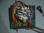
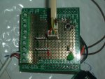
In the bright light of day i could see what appeared to be puncture marks in the 12v wire from the board connector to the terminal block, where i plan to connect the transducers. (Orange wire in photo). From the location this would have been punctured by a messy solder joint on an ADC input pin. So this is the most likely source of 12V on an input pin.

This makes sense with BB' s description of the cause of heating below.

I installed the new chip carefully, and connected the protoboard with more care, adding a bit of duct tape to the 12v (needed for the pressure transducers) to provide more security (in photo).

I waited for the heating - no heating. Whew. Maybe that was it.

I have set the transducer connectors up on ADC 0, 1, 2, and 3. I have analogue pressure transducers, and since both the DS18B20 and the PWM accelerometer (my other threads) worked on the 18X ADC 0 and 1, I just assumed they would work on the same input of the 28X1. I figured that would give me more flexibility if i wanted to use an analogue sensor later on, or the same configuration for other projects.

Well, when i connected up the Accelerometer and DS18B20 to ADC 2 and 3 on the 28X and got nothing. I knew i had not cooked the chip, so i went looking through the manual (again).

I think i have the answer, but i don't want to do more soldering (spot the mistakes in my photos) until i have confirmation:

Answer:
On the 18X, the ADC 0, 1, and 2 also double as digital inputs, and are defined as such when you use the pulsin or Readtemp command.

On the 28X1 they are discrete ADC inputs. They can be configured via the porta command to be an on/off digital inbut, but not for readtemp and pulsin. If i want to use readtemp and puulsin i have to rewire to in 0 to 7, which is leg 11 to 18, but not use the I2C pins because i am using them for the I2C display and data logging.

Before i do more messy soldering does this sound right?

Maybe the other chip that got cooked didn't really get cooked, surviving 12V on the input pins. That would be a bonus. Will let you know once i have passed this next hurdle.

Michael
 

Attachments

Last edited:

BeanieBots

Moderator
Your understanding of the input pins required for a DS18B20 on a 28X1 are correct.
Some inputs on some chips (I can't remember which) can cope with 12v so you might have got away with it but if the chip got hot, then probably not.
 

Ralpht

New Member
Looking at at your pictures, what makes for messy soldering, other than inexperience of course, is wrong size wire and soldering iron bit size.

If I may offer a suggestion, if it is available in your area, try to use wire wrap wire. It is very thin, has tough insulation and is very easy to solder, with the absolute minimum of solder required to make a good joint. A smaller soldering iron bit can then be used which will also help prevent damage elsewhere.

Less chance then of damaging the insulation on adjacent wiring, as you no doubt did by accident.

I
 

Ralpht

New Member
Dan,

I just noticed you're in Sydney. Tricky Dicky or Jaycar should have wire wrap wire, reasonably cheaply. Sometimes called Kynar wire.

I use it all the time on prototypes and makes for a tidier layout. As well, even though it looks very thin, it can carry an amp, which is much more than required for digital interconnects and most normal output requirements.
 

Michael V

Senior Member
Success !!!!

Well, i rewired the DS18B20 and the all important accelerometer pins to digital inputs. At first i didn't know what to call them because the analogue pins are 0, 1, 2, and 3, what could the digital ones be called. But true to Picaxe simplicity they are also called, 0, 1, 2, 3 etc. I guess when you use pulsin or readtemp on the 28x1 it knows to go to the digital input. As long as Readadc goes to the analogue inputs i should be OK!

So it worked, as it did on the 18X.

Ralph,
thanks for the tip on the wire wrap wire. I'd seen it there in Jaycar (Blacktown, helpful people) and i thought it was for wrapping wire, and couldn't think why you would want to do that. But now i know it is wire you can wrap with, i'll have a closer look. (Guess there are 10 types of people....)

For those interested the code is below (much plagiarised form Wizard).

The idea is that the accelerometer monitors the angle of the excavator boom. It has X and Y PWM output, but i really only need one of them. When the boom is up, it double checks with a consecutive reading, and declares a "Boom High" state to the LCD and the computer. When the boom falls past a certain point (Symbol = limit) then it double checks the second reading (learned this from Moey on the DS18B20 thread) takes the readings from two pressure transducers, calculates the differential pressure, and displays this and the temp on the LCD screen.

Code:
'AXE110 PICAXE-18X - New Datalogger Mission Program
'Automatically generated by Wizard

'LED will flash green as readings are taken.

'Data can be retrieved after mission (LED red) by Datalink tool (F9).
'Use Datalink options: Baud rate - 4800, Sensors - 4, Send G - Enabled

' *******************
' ***** Options *****
' *******************

'Title - Event based Diff Pressure
'Date  - 27/11/2007
'Time  - 11:28:10 AM

'Options Selected
'Sensors:
'Sensor 0 - Tank (Analogue 0-5V)
'Sensor 1 - Manifold( Analogue 0-5V)
'Sensor 2 - Boom (PWM)
'Sensor 3 - Temperature (Digital - DS18B20)

'Memory:
'No of readings = 105
'4 x 24LC256

'Outputs:
'AXE111 EE WP on output6

'Logging Period:
'DS1307 RTC
'Hours:  1 Mins:  15 Secs:  0 

' ********************
' ***** Symbols  *****
' ********************

'Symbol definitions
symbol data0 = b0
symbol data1 = b1
symbol data2 = w5		'(b10 + b11)
symbol data3 = b3
symbol top_address = w2 '(b4 + b5)
symbol address = w3     '(b6 + b7)
symbol temp_word = w4   '(b8 + b9)

symbol temp_byte = b10
symbol temp_byte1 = b11
symbol temp_byte2 = b12
symbol temp_byte3 = b13
symbol hours = b11
symbol mins = b12
symbol secs = b13
symbol day = b0
symbol month = b1
symbol COM = 44         'comma
symbol RET = 13         'carriage return
symbol LFEED = 10          'line feed

Symbol limit = 350 'Boom Angle Limit - determied on site
symbol boom = w4

'Preload sensor names and title into data memory
EEPROM 0,(0,0)
EEPROM 16,("Diff Press")
EEPROM 32,("Time")
EEPROM 48,(" ")
EEPROM 64,("Temperature")
EEPROM 80,("Event based Diff Pressure")


' ***************************
' ***** Initialisation  *****
' ***************************

init:
	high 5 ' write protect eeprom
	high 6 ' write protect eeprom
'reload the last address from data memory
	read 0,b6
	read 1,b7


' *********************************
' ***** Main loop - read data *****
' *********************************


	i2cslave $50,i2cfast,i2cbyte 	‘set up i2cslave for LCD	
	pause 500 		‘ wait for display to initialise
	writei2c  ($80,$0c)	'0x0c = CLS & first line

main:	

mainup:	
' test for 2 consecutive readings above limit
	pulsin 0,1,boom
	if boom < limit then 
		pause 250
		sertxd ("down ",#boom,13,10)
		goto mainup
	endif	
		pulsin 0,1,boom
	if boom < limit then goto mainup

' If it gets to this point the boom is up.	
		sertxd ("up   ",#boom,13,10)
 	writei2c ($80, $0d)		'Goto beginning of first line	
	writei2c  ($80,"Boom     High ")

maindown:	
' test for 2 consecutive readings below limit before saying down
	pulsin 0,1,boom
		pause 250
	if boom > limit then 
	
		sertxd ("up ",#boom,13,10)
		goto maindown
	endif	
		pulsin 0,1,boom
	if boom > limit then goto maindown

' If it gets to this point the boom has gone from up to down.

'Write Boom Drop to LCD
	writei2c  ($80,$0c)	'$0c =  Clear display goto first line

	writei2c  ($80,"Boom Drop ")
	pause 50	

	
' Capture the data	
	readadc 0,data0	'Pressure Tank
	pause 30
	readadc 1,data1	'Pressure Return Manifold
	pause 30
	let temp_byte = data1 - data0

	readtemp 2,data3			'Read Temp (Includes delay)
	pause 30

'Display change onPC
		sertxd ("DP ",#temp_byte," Temp ",#data3,13,10)	
'Display Data on Modtronix LCD.
	writei2c  ($8a,2,1)	'goto row 2 pos 1	
	writei2c  ($80,"DP ")
	bintoascii temp_byte,temp_byte1,temp_byte2,temp_byte3
	writei2c  ($80, temp_byte1,temp_byte2,temp_byte3)
	pause 30	
	writei2c  ($80," Temp ")	
	bintoascii data3,temp_byte1,temp_byte2,temp_byte3
	pause 30
	writei2c  ($80, temp_byte1,temp_byte2,temp_byte3)	

	
'send to PC


	Pause 1000
	writei2c  ($80,$0d)	'0x0d =  first line
	writei2c  ($80,"Boom Low ")	

'*** At this point test for time condition


'**** if met, save the data go to a subrioutine

goto main

' *****************************
' ***** Now Save the Data *****
' *****************************	

' ***** I have not done anything on this yet, just happy that the loop works *****


'Now save the data
save_data:
	low 5 ' write enable eeprom

	low 6 ' write enable eeprom

'4x 24LC256. Input0 in IC0, input1 in IC1
'4x 24LC256. Input2 in IC2, input3 in IC3
	if address > 16383 then memory_full
	i2cslave %10100000, i2cslow, i2cword
	writei2c address,(data0)
	pause 10
	readi2c address,(temp_byte)
	if temp_byte <> data0 then ee_error

	i2cslave %10100010, i2cslow, i2cword
	writei2c address,(data1)
	pause 10
	readi2c address,(temp_byte)
	if temp_byte <> data1 then ee_error

	i2cslave %10100100, i2cslow, i2cword
	writei2c address,(data2)
	pause 10
	readi2c address,(temp_byte)
	if temp_byte <> data2 then ee_error

	i2cslave %10100110, i2cslow, i2cword
	writei2c address,(data3)
	pause 10
	readi2c address,(temp_byte)
	if temp_byte <> data3 then ee_error

'increment address and save in data memory
inc_address:
	high 5 ' write protect eeprom

	high 6 ' write protect eeprom

	let address = address + 1
	write 0,b6
	write 1,b7
	if address > 1050 then memory_full


' ***********************
' ***** Time Delays *****
' ***********************

'Now do time delay
'Read time now
read_rtc_now:
	i2cslave %11010000, i2cslow, i2cbyte
	readi2c 0,(secs,mins,hours)

'Convert to decimal then add offset
	gosub bcd_decimal

	let data0 = secs
	let data1 = mins
	let data2 = hours

Add_Secs:
	let data0 = data0 + 0
	if data0 < 60 then Add_Mins
'Secs is now greater than 60 so add 1 to minute instead
	let data0 = data0 - 60
	let data1 = data1 + 1

Add_Mins:
	let data1 = data1 + 15
	if data1 < 60 then Add_Hours
'Mins is now greater than 60 so add 1 to hour instead
	let data1 = data1 - 60
	let data2 = data2 + 1

Add_Hours:
	let data2 = data2 + 1
	if data2 < 24 then read_rtc
'Hours is now greater than 24 so correct
	let data2 = data2 - 24

'Read rtc to test alarm'
read_rtc:
	i2cslave %11010000, i2cslow, i2cbyte
	readi2c 0,(secs,mins,hours)

	gosub bcd_decimal

	if secs <> data0 then read_rtc
	if mins <> data1 then read_rtc
	if hours <> data2 then read_rtc

'now do next reading
	goto main
At this stage i am happy that the "event detection" part of the program works. Next i will try the "Owin" and "owout" commands for the temp chip, because for sure the boom will be above the limit point for more than a second, and i can use that time for "conversion".

I am also really happy that after i got it to work, i replaced the new chip with my original chip, and that worked too! So it was not cooked after all! That is one hardy little device!

I could not have got this far without this forum, that's for sure!

Next Challenge - Record the Event
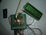
My next challenge is to record the time from the Ds1307 clock, and record data into 4x 24LC256 eeprom chips. That is what the header pins on the proto board are for (picture) The Modtronix LCD is connected with the Micro Match connector, but the micro match pins are too close together for me to do anything with for the clock and memory board.

Readings will be time prompted, eg every minute, or every five or ten minutes, but different things may happen at different times of the day, and temperatures will vary, affecting the pressure. Also i may only get to the machine once per month. That's why i need to record the time of the event.

In looking through the Wizard generated datalogger code for four chips, it seems to put one byte for each reading in each chip. That's great when the info is only one byte, but i want to record 1) The DP (byte), the temperature (byte) and also the time (to minute) and date, which is going to be a lot more bytes. Actually just writing to a single chip would be enough at this stage, and i can graduate to four chips later. Any tips on how to do this easily and efficiently?

Also in the datalogger wizard, the sequence is to keep logging for the preset number of readings, the "mission", then stop. However, i am happy that if i don't get to the machine regularly, that it keeps overwriting the old data, since it is the most recent data that is the most relevant from a maintenance perspective. Duplicated old data can be easily excluded , because of the time and date stamping.

I figure i will retrieve data using the "retrieve unknown data" code, so i'll just get everything on the chips.

Any advice?

Thanks once again for your help.
 

Attachments

Top