I have a Picaxe circuit with an EM406a GPS attached to it. I have had about 50 of the circuits using Picaxe 18x's running perfectly for the past 3 years. They power up the GPS once an hour, take a reading, update a DS1307, then power the GPS down again.
I have to build some more of them but have discovered that the 18x is no longer available, so I have been rewriting the program to convert to 18M2+. (Not as simple as the manuals make out!)
After scratching my head over strange behaviour for a couple of days I have finally worked out that often when I power up the GPS, the Picaxe resets.
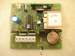
I have a 12V 2A regulated switchmode plugpack driving the circuit. The circuit has a 7805 voltage regulator with a 1000uF cap plus a 103 filter cap across it. The Picaxe has a 103 filter cap close to the VCC pin. I have attached a scope (Velleman HPS5) to the Picaxe VCC pin and it shows no glitches when the GPS powers up (although it may not be fast enough to catch them).
I have shrunk the program down to the following and tested it repeatedly on an 18x and an 18M2+. It runs perfectly on the 18X. On the 18M2+ every 5 or 6 loops the first debug repeats. ie. the debug counter at the top increments several times but b0 remains at 1, and b1 resets to 0, then eventually the program proceeds to the second debug output. The only thing that could be causing that is the picaxe resetting as a result of the GPS switching on.
Are there any known issues with the 18M2+ being sensitive to power fluctuations please? I thought from reading the specs that the M2 parts were supposed to tolerate even lower voltages that the older parts.
do
b0 = 1
debug b0
wait 1
high b.7 'turn on GPS
b0 = 2
debug b0
wait 1
low b.7
b1 = $ff ' resets to 0 every now and then
loop
I have to build some more of them but have discovered that the 18x is no longer available, so I have been rewriting the program to convert to 18M2+. (Not as simple as the manuals make out!)
After scratching my head over strange behaviour for a couple of days I have finally worked out that often when I power up the GPS, the Picaxe resets.
I have a 12V 2A regulated switchmode plugpack driving the circuit. The circuit has a 7805 voltage regulator with a 1000uF cap plus a 103 filter cap across it. The Picaxe has a 103 filter cap close to the VCC pin. I have attached a scope (Velleman HPS5) to the Picaxe VCC pin and it shows no glitches when the GPS powers up (although it may not be fast enough to catch them).
I have shrunk the program down to the following and tested it repeatedly on an 18x and an 18M2+. It runs perfectly on the 18X. On the 18M2+ every 5 or 6 loops the first debug repeats. ie. the debug counter at the top increments several times but b0 remains at 1, and b1 resets to 0, then eventually the program proceeds to the second debug output. The only thing that could be causing that is the picaxe resetting as a result of the GPS switching on.
Are there any known issues with the 18M2+ being sensitive to power fluctuations please? I thought from reading the specs that the M2 parts were supposed to tolerate even lower voltages that the older parts.
do
b0 = 1
debug b0
wait 1
high b.7 'turn on GPS
b0 = 2
debug b0
wait 1
low b.7
b1 = $ff ' resets to 0 every now and then
loop
Last edited: