slimplynth
Senior Member
After owning a 28X2 3v for some months, was forced to crack it open last night.. couldn't put my hands on the 5V version; also as I've never had to power anything at 3V I thought best to have a go.
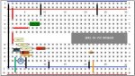
Have tested and the circuit gives a steady 1.89V supply to the 28X2 which is close to the lower limit stated in Manual 1 - as low as 1.8V
The Regulator is an LM317T - I'm not sure what this setup is going to be used for... but it's likely the 28X2 will be configured to output to as many 4066's as I can breadboard (just bought a big 'un)
From the Pebble below, Is there a problem with using a 100uf capacitor to ground? it was the lowest value I could put in last night..
...I guess basically what I'm asking is, "Would you be happy to breadboard your one and only 3V-28X2 like this? If not, what would you change?"
Cheers
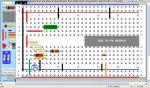
Edit: Amended pebble below as per Westaust & BB's posts...
Have tested and the circuit gives a steady 1.89V supply to the 28X2 which is close to the lower limit stated in Manual 1 - as low as 1.8V
The Regulator is an LM317T - I'm not sure what this setup is going to be used for... but it's likely the 28X2 will be configured to output to as many 4066's as I can breadboard (just bought a big 'un)
From the Pebble below, Is there a problem with using a 100uf capacitor to ground? it was the lowest value I could put in last night..
...I guess basically what I'm asking is, "Would you be happy to breadboard your one and only 3V-28X2 like this? If not, what would you change?"
Cheers
Edit: Amended pebble below as per Westaust & BB's posts...
Code:
Wire||74|44|21||11|#FF0000|3|11||10|
Wire||47|17|21||11|#000000|16|11||10|
Wire||74|209|21||11|#FF0000|3|11||10|
Resistor|1000|105|339|1|Resistor|R?||3||IC||
Wire||130|363|12||11|#FF9900|3|11||10|
Wire||76|180|11||11|#FF0000|4|11||10|
Capacitor|1K63: 100nf|185|142|1|Capacitor|C?||3|1|||cap_131
Wire||290|17|21||11|#000000|3|11||10|
Wire||317|402|21||11|#000000|2|11||10|
Capacitor|100uf|109|404|2|Capacitor|C?||2|3|||cap_322
Note||82|252|1||||1||1 - LM317T||NOTEPAD_11
Note||108|284|1||||1||2 - LM317T||NOTEPAD_11
Note||137|311|1||||1||3 - LM317T||NOTEPAD_11
IC||471|210|2|28X2 - 3V - PIC 18F25K20|U?|||DIP28|IC||DIP28_2
Wire||586|402|21||11|#000000|2|11||10|
Wire||613|402|21||11|#FF9900|3|11||10|
Wire||640|17|21||11|#000000|3|11||10|
Resistor|10000|213|311|1|Resistor|R?||3||IC||
Wire||91|374|22||11|#00A060|4|11||10|
Capacitor|100nF|589|335|3|Capacitor|C?||1|4|||cap_413
Wire||158|374|23||11|#000000|3|11||10|
BREADBOARDSTYLE=BB12
SHOWTHETOPAREA=false
Attachments
-
 118.7 KB Views: 52
Last edited: