Pb switchmode charger/discharger.

gwatpe

New Member
some typical waveforms

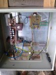
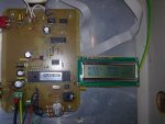
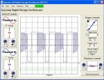
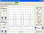
I have attached some typical waveforms to expect from say a buck converter, that I have measured from one of my converters. One is the voltage on the drain wrt the source, and a second is the voltage on the mosfet gate wrt the source. There is ringing from the inductor that appears on the drain. The inductor has a resistance of about 10milliohms, and is good for 1000W. approx 20A@50V.

The waveforms are sharp, and this leads to high converter efficiency, as there is low tri-state conduction in the device. It is essential to have good supply bypassing, for the expected frequencies.

The gate was driven with a 10V rail, and the probe was X10.
there was approx 52V supply at the time. the switching speed was 16.67kHz.

This converter is used as a windmill MPPT at the moment.

Gordon.

PS: there is no resistor in the mosfet gate drive.
 

Attachments

Last edited:

Janne

Senior Member
Update on this mppt controller project.. It's now been on test use for a couple of weeks. Initially I had problems with the mosfets, as I blew the remaining one the moment I connected it to the battery. I guess the sparking, that occured while hooking it up caused a voltage spike which fried the gate insulator = all pins nice and shorted together. After replacing both of them with fresh ones, and using a disconnect switch to hook it up to the battery again, it worked without a hitch.

During this testing, it has seen peak output currents of over 40A to the battery, and sustained maxium currents of 25A, which is currently the point where the mechanical furling kicks in and limits the power.

To wrap it all up in a couple of conclusions.. First of all, using the transformer to drive the mosfet gate is a big pain in the backside, getting it to work nicely from duty cycles of 0 to 95 is not as easy as some of the application notes fool you to believe. I think a better idea would be to use an isolating dc / dc converter + opto coupler to drive the gate, like they do in the Open Re-Volt electric car controller(I only hope I would have found that project earlier, it would have helped on many of the problems I came across on this project. http://ecomodder.com/wiki/index.php/ReVolt) Second, using an analogue stage to generate the pwm pulses seemes a bit awkward. I think a better way would be to use a more powerful controller, for example, a raw programmed pic or avr for the job, and just use a software PI(D) loop to control the duty cycle based on the measured current. A drawback in this configuration would be, that using high switching frequencies would no longer be viable without seriously sacrificing resolution, but I think the 100kHz I went with was a bit on the high side anyway. It would have been easier to settle for lower frequency, and bigger passive components.

In all, it still seems well worth the effort. The windmill now much better follows the optimal speed curve of the rotor, which keeps the efficiency near the optimal to the point where the mechanical furling starts to limit the output. It'll be interesting to see how well it is really doing, once I get around and install the datalogger onto it again. My trusty old datalogging laptop IBM A30 got fried, so I think I'm going to need to make a new logger based on the µALFAT module I bought a few months back. Which should also endure the sub-zero temperatures much better, than the poor old laptop :)

Attached is a couple of pictures of the setup, and the source code for 40x1 for anyone interested, and also as a backup for myself.
 

Attachments

Janne

Senior Member
Better late than never :)

About the mppt, after initial commissioning it has been quite boring.. Been happily bucking down for almost 2 years now. Only "maintenance" I had to do was to upload a new output table, as I crashed a blade and needed to cut them down in leghth, essentially reducing power available per rpm.
 

BeanieBots

Moderator
Glad to hear it's still working well and thanks for the update.
I now have a 2.4kW installation but I cheated and bought a ready-made inverter in order to be compliant so that I qualify for the feed in tarrif.
 
Top