One more proximity sensor

edmunds

Senior Member
Dear all,

I did destroy the only two IR proximity sensors I had the other day, so did not get to a state where I could report how accurate and how sensitive to ambient they were :(. Will get some more to complete the tests.

However, the long awaited VL6180X arrived today. 10 of them, so some margin for error :).

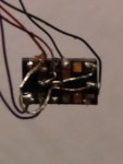
I have now been playing with it for an hour or so. I managed to solder it well with the recommended caps and resistors as per data sheet. I added an N4001 in series with the positive terminal from regulated 3.3V supply, so I'm running my axe091 at 2.72-2.73V. Picaxe40x2 is happily downloading a program. I have strange behaviour of the sensor, though.

With i2c address of 0x52, I get seemingly random numbers from any register I try to read. With any other address (just had to try it given my trivial mistake the other day), I get 255. As I understand, this means I'm talking to the thing with the address of 0x52, but it is talking rubbish back to me. Not the register number referred to (which I have seen before), but different number every loop. There are no other components involved apart from I2C pull-ups and already mentioned caps and 47k resistors with the sensor. Here is the code:

Code:
#picaxe40x2
#no_data
#no_table

Symbol I2CSpeed = i2cslow

Symbol VL6180X = 0x52    'ALS/proximity sensor

Symbol GPIO1 = B.0
Symbol GPIO1Pin = pinB.0


init:

  hi2csetup i2cmaster, VL6180X, I2CSpeed, i2cbyte      'Announce there will be I2C
  hi2cout 0x010, (0)                                                        'Disable (Hi-Z) GPIO0
  hi2cout 0x011, (%00010000)                                        'Set GPIO1 as interrupt pin
  hi2cout 0x014, (0)                                                        'Disable all interrupts for testing
'  hi2cout 0x2A3, (1)                                                        'Interleaved mode of range and ALS measurements
  hi2cout 0x018, (%00000001)                                        'Start range measurements only
  hi2cout 0x01B, (%00000010)                                        '20ms in between measurements
  hi2cout 0x02D, (0)                                                        'Disable signal-to-noise, range-ignore and convergence features

main:

  hi2cin 0x000, (b0)  
  sertxd (#b0, LF, CR)
  pause 2000

goto main

Any ideas what to look for?

Thank you for your time,

Edmunds
 

edmunds

Senior Member
FullSizeRender.jpg

Here is the soldering part. Just in case. If it is possible to actually distinguish anything.

Edmunds
 

bgrabowski

Senior Member
VL6180X Test Prog

I did some preliminary coding last year when I saw these sensors on the Mouser website. They work brilliantly and are not greatly affected by surface they detect. For example they gave virtually the same reading for a black and a white surface at 100mm. The main drawback is that readings take about 15ms depending on the proximity of the object detected and significantly longer than that if there is nothing in range. They output the distance directly in mm from about 10mm to about 200mm and seem to be accurate to about 3mm mid-range.

Here is the Picaxe code I used (some of the delays may be shortened without affecting the operation):

Code:
'TOF Sensor Test for PICAXE 18M2
'Part ref VL6180X
'operating at default 8MHz
'Read sensor and output PWM in proportion to reading
'Version of Programming Editor Version Used 6.0.7.5 (Beta)
'B Grabowski
'Version 2
'Jan 2015
'719 bytes used out of 2048
'
'PORT ASSIGNMENTS
'b.0 = LCD output
'b.1 = I2C SDA
'b.4 = I2C SCL
'b.6 = PWM output
'
'DIRECTIVES
#picaxe 18M2     'code optimised for Picaxe 18M2
'
'DECLARE SYMBOLS FOR CONSTANTS
symbol serLCD = b.0
symbol PWMpin = b.6
'
'DECLARE SYMBOLS FOR VARIABLES
'Common variables
symbol Data_Byte = b0   'Holds 8 bit data
symbol Distance_mm = b1 'Holds distance reading in mm
symbol Address_16 = w3  'Holds 16 bit address for read/write
symbol voltage = w4     'Holds calculated PWM duty (0-407)
'
'************************************************************************
'                        INITIALISATION
'************************************************************************
init:
pause 1000               'Time for LCD to initialise
serout serLCD,N2400,(254,1,"TOF Sensor Test")
pause 3000
'
'Set up I2C bus
hi2csetup i2cmaster,%01010010,i2cfast,i2cword  'slave address 52 Hex
'
'Initialise TOF sensor
Address_16 = 0x16    'Reset status byte register address
GoSub Read_I2C       'Returns contents of register Address_16 in Data_Byte
serout serLCD,N2400,(254,1,"Reset = ",#Data_Byte)  'Display on LCD
pause 30
serout serLCD,N2400,(254,192,"Initialising...")
pause 30
'
GoSub Init_I2C       'Load the required register settings
'
'Now confirm initialisation has taken place
Address_16 = 0x16    'Reset status byte register address
GoSub Read_I2C       'Returns contents of register Address_16 in Data_Byte
If Data_Byte <> 0 Then  'Check fresh out of reset status = 0
    serout serLCD,N2400,(254,1,"  Init Failed")    ' Display error message
    do 
    loop while b1=b1        ' Freeze on error message
Else      ' Display init success message
    serout serLCD,N2400,(254,1,"Init Successful") 
    pause 3000      'for 3 sec  
End If
'Start PWM output at half duty
pwmout PWMpin, 101, 203     'Set PWM output 9804Hz - duty (0-407)
'
Read_Sensor:
GoSub Single_Shot_Read      'Take a reading in single-shot mode
'Note: ensure 10ms min between readings
voltage = Distance_mm - 30 * 4  'Calculate PWM duty
pwmduty PWMpin,voltage      'Output PWM proportional to sensed distance
serout serLCD,N2400,(254,1,"Reading = ",#Distance_mm, " mm    ")
pause 30
serout serLCD,N2400,(254,192,"PWM Duty = ",#voltage,"/407  ") 'Update LCD
pause 30
GoTo Read_Sensor            'Loop forever    
'
loop1:
goto loop1                  'Infinite loop to prevent drop through to subroutines
'************************************************************************
'                          SUBROUTINES
'************************************************************************
' Enter with target register as Address_16 
' Return with data from register in Data_Byte 
Read_I2C:                                   
hi2cin Address_16,(Data_Byte)
Return        
' ***********************************************************************
'Enter with target register as Address_16 and data to write in Data_Byte
Write_I2C:        
hi2cout Address_16,(Data_Byte)
pause 5                 ' Allow time for allocation of byte
Return  
' ***********************************************************************
'Perform a single-shot read on the VL6180X 
'Return with reading in Distance_mm
Single_Shot_Read:                                    
Address_16 = 0x4d                   ' Check device is ready (Bit0 set)
'
Wait_Ready_Read:
GoSub Read_I2C
If bit0 = 0 then Wait_Ready_Read    ' Wait for device to become ready
' 
Address_16 = 0x0018
Data_Byte = 0x01                    ' Start a range measurement
GoSub Write_I2C 
Address_16 = 0x4f                   ' Check measurement complete(Bit2 set)
'
Wait_Sample_Ready:
GoSub Read_I2C
If bit2 = 0 Then Wait_Sample_Ready  ' Wait for measurement to be completed        
'
Address_16 = 0x62                   ' Read the range into Data_Byte
GoSub Read_I2C
'
Distance_mm = Data_Byte             ' Save the measured distance in mm 
Address_16 = 0x15 
Data_Byte = 0x07                    ' Clear the interrupt status
GoSub Write_I2C 
Return                              ' Return with reading in Distance_mm
'************************************************************************
' Load the required settings onto the VL6180X
 Init_I2C:              
    ' Mandatory register settings
        Address_16 = 0x0207
	  Data_Byte = 0x01
    GoSub Write_I2C
        Address_16 = 0x0208
	  Data_Byte = 0x01
    GoSub Write_I2C
        Address_16 = 0x0096
	  Data_Byte = 0x00
    GoSub Write_I2C
        Address_16 = 0x0097
	  Data_Byte = 0xfd
    GoSub Write_I2C
        Address_16 = 0x00e3
	  Data_Byte = 0x00
    GoSub Write_I2C
        Address_16 = 0x00e4
	  Data_Byte = 0x04
    GoSub Write_I2C
        Address_16 = 0x00e5
	  Data_Byte = 0x02
    GoSub Write_I2C
        Address_16 = 0x00e6
	  Data_Byte = 0x01
    GoSub Write_I2C
        Address_16 = 0x00e7
	  Data_Byte = 0x03
    GoSub Write_I2C
        Address_16 = 0x00f5
	  Data_Byte = 0x02
    GoSub Write_I2C
        Address_16 = 0x00d9
	  Data_Byte = 0x05
    GoSub Write_I2C
        Address_16 = 0x00db
	  Data_Byte = 0xce
    GoSub Write_I2C
        Address_16 = 0x00dc
	  Data_Byte = 0x03
    GoSub Write_I2C
        Address_16 = 0x00dd
	  Data_Byte = 0xf8
    GoSub Write_I2C
        Address_16 = 0x009f
	  Data_Byte = 0x00
    GoSub Write_I2C
        Address_16 = 0x00a3
	  Data_Byte = 0x3c
    GoSub Write_I2C
        Address_16 = 0x00b7
	  Data_Byte = 0x00
    GoSub Write_I2C
        Address_16 = 0x00bb
	  Data_Byte = 0x3c
    GoSub Write_I2C
        Address_16 = 0x00b2
	  Data_Byte = 0x09
    GoSub Write_I2C
        Address_16 = 0x00ca
	  Data_Byte = 0x09
    GoSub Write_I2C
        Address_16 = 0x0198
	  Data_Byte = 0x01
    GoSub Write_I2C
        Address_16 = 0x01b0
	  Data_Byte = 0x17
    GoSub Write_I2C
        Address_16 = 0x01ad
	  Data_Byte = 0x00
    GoSub Write_I2C
        Address_16 = 0x00ff
	  Data_Byte = 0x05
    GoSub Write_I2C
        Address_16 = 0x0100
	  Data_Byte = 0x05
    GoSub Write_I2C
        Address_16 = 0x0199
	  Data_Byte = 0x05
    GoSub Write_I2C
        Address_16 = 0x01a6
	  Data_Byte = 0x1b
    GoSub Write_I2C
        Address_16 = 0x01ac
	  Data_Byte = 0x3e
    GoSub Write_I2C
        Address_16 = 0x01a7
	  Data_Byte = 0x1f
    GoSub Write_I2C
        Address_16 = 0x0030
	  Data_Byte = 0x00
    GoSub Write_I2C
    '
    ' Recommended register settings
        Address_16 = 0x0011
	  Data_Byte = 0x10     ' Enables polling for new sample ready
    GoSub Write_I2C
        Address_16 = 0x010a
	  Data_Byte = 0x30     ' Set the average sample period
    GoSub Write_I2C
        Address_16 = 0x003f
	  Data_Byte = 0x46     ' Sets the light/dark gain upper nibble
    GoSub Write_I2C
        Address_16 = 0x0031
	  Data_Byte = 0xff     ' Sets no of measurements for calibration
    GoSub Write_I2C
        Address_16 = 0x0040
	  Data_Byte = 0x63     ' Set ALS integration time to 100ms
    GoSub Write_I2C
        Address_16 = 0x002e
	  Data_Byte = 0x01     ' Perform single temperature calibration
    GoSub Write_I2C
    '
    ' Optional register settings
        Address_16 = 0x001b
	  Data_Byte = 0x09     ' Set inter-measurement period to 100ms
    GoSub Write_I2C
        Address_16 = 0x003e
	  Data_Byte = 0x31     ' Set ALS inter-measurement period to 500ms
    GoSub Write_I2C    
        Address_16 = 0x0014
	  Data_Byte = 0x24     ' Config interrupt on new sample ready event
    GoSub Write_I2C
    ' Indicate settings have been loaded
        Address_16 = 0x16
	  Data_Byte = 0x00     ' Write 0 to Reset status byte register
    GoSub Write_I2C    
    Return
'************************************************************************
 

edmunds

Senior Member
I did some preliminary coding last year when I saw these sensors on the Mouser website. They work brilliantly and are not greatly affected by surface they detect. For example they gave virtually the same reading for a black and a white surface at 100mm. The main drawback is that readings take about 15ms depending on the proximity of the object detected and significantly longer than that if there is nothing in range. They output the distance directly in mm from about 10mm to about 200mm and seem to be accurate to about 3mm mid-range.

Here is the Picaxe code I used (some of the delays may be shortened without affecting the operation):
Thank you so much! I'll see how I can use your code. This forum continues to prove being a goldmine :).

I'm a bit concerned about exactly the issue you mention - the time the measurement takes. But it remains to try it out for my application.


Thanks a million,

Edmunds
 

edmunds

Senior Member
How did you deduct, you had to use i2cword and not i2cbyte? Mots of the registers are byte registers and while some are word, how would you decide when to use byte and when word data size?


Edmunds
 

inglewoodpete

Senior Member
In the case i2c, Byte and Word refers to the addressing capability. i2c always sends and receives data as bytes. However, if the slave has mode than 256 internal addressable registers or memory locations, it will need a 16-bit address pointer to reference all of them.

Check the data sheet for the VL6180X (you are going to have to anyway). You will see that the last addressable register is at 0x2A3, requiring more than a byte to address it.
 

edmunds

Senior Member
In the case i2c, Byte and Word refers to the addressing capability. i2c always sends and receives data as bytes. However, if the slave has mode than 256 internal addressable registers or memory locations, it will need a 16-bit address pointer to reference all of them.

Check the data sheet for the VL6180X (you are going to have to anyway). You will see that the last addressable register is at 0x2A3, requiring more than a byte to address it.
Thanks, that explains a thing or two :). For some reason I thought this refers to data, not the register address.

Edmunds
 

edmunds

Senior Member
Got it working with the code from @bgrabowski. Edited out the pwm part and re-wrote to sertxd instead of serout for LCD. Posted below in case somebody finds it useful now or some years from now :).

Code:
#picaxe 40x2
#no_data
#no_table


symbol Data_Byte = b0   'Holds 8 bit data
symbol Distance_mm = b1 'Holds distance reading in mm
symbol Address_16 = w3  'Holds 16 bit address for read/write
'
'************************************************************************
'                        INITIALISATION
'************************************************************************
init:
  pause 1000               'Time for LCD to initialise
  sertxd ("TOF Sensor Test", LF, CR)
  pause 3000
'
'Set up I2C bus
  hi2csetup i2cmaster,%01010010,i2cfast,i2cword  'slave address 52 Hex
'
'Initialise TOF sensor
  Address_16 = 0x16    'Reset status byte register address
  GoSub Read_I2C       'Returns contents of register Address_16 in Data_Byte
  sertxd ("Reset = ",#Data_Byte, LF, CR)  'Display on LCD
  pause 30
  sertxd ("Initialising...", LF, CR)
  pause 30
'
  GoSub Init_I2C       'Load the required register settings
'
'Now confirm initialisation has taken place
  Address_16 = 0x16    'Reset status byte register address
  GoSub Read_I2C       'Returns contents of register Address_16 in Data_Byte
  If Data_Byte <> 0 Then  'Check fresh out of reset status = 0
      sertxd ("Init Failed", LF, CR)    ' Display error message
      do 
      loop while b1=b1        ' Freeze on error message
  Else      ' Display init success message
    sertxd ("Init Successful", LF, CR) 
    pause 3000      'for 3 sec  
  End If

Read_Sensor:
  GoSub Single_Shot_Read      'Take a reading in single-shot mode
'Note: ensure 10ms min between readings
  sertxd ("Reading = ",#Distance_mm, " mm", LF, CR)
  pause 30
  GoTo Read_Sensor            'Loop forever    
'
loop1:
goto loop1                  'Infinite loop to prevent drop through to subroutines
'************************************************************************
'                          SUBROUTINES
'************************************************************************
' Enter with target register as Address_16 
' Return with data from register in Data_Byte 
Read_I2C:                                   
  hi2cin Address_16,(Data_Byte)
Return        
' ***********************************************************************
'Enter with target register as Address_16 and data to write in Data_Byte
Write_I2C:        
  hi2cout Address_16,(Data_Byte)
  pause 5                 ' Allow time for allocation of byte
Return  
' ***********************************************************************
'Perform a single-shot read on the VL6180X 
'Return with reading in Distance_mm
Single_Shot_Read:                                    
  Address_16 = 0x4d                   ' Check device is ready (Bit0 set)
'
Wait_Ready_Read:
  GoSub Read_I2C
  If bit0 = 0 then Wait_Ready_Read    ' Wait for device to become ready
' 
  Address_16 = 0x0018
  Data_Byte = 0x01                    ' Start a range measurement
  GoSub Write_I2C 
  Address_16 = 0x4f                   ' Check measurement complete(Bit2 set)
'
Wait_Sample_Ready:
  GoSub Read_I2C
  If bit2 = 0 Then Wait_Sample_Ready  ' Wait for measurement to be completed        
'
  Address_16 = 0x62                   ' Read the range into Data_Byte
  GoSub Read_I2C
'
  Distance_mm = Data_Byte             ' Save the measured distance in mm 
  Address_16 = 0x15 
  Data_Byte = 0x07                    ' Clear the interrupt status
  GoSub Write_I2C 
Return                              ' Return with reading in Distance_mm
'************************************************************************
' Load the required settings onto the VL6180X
 Init_I2C:              
    ' Mandatory register settings
        Address_16 = 0x0207
	  Data_Byte = 0x01
    GoSub Write_I2C
        Address_16 = 0x0208
	  Data_Byte = 0x01
    GoSub Write_I2C
        Address_16 = 0x0096
	  Data_Byte = 0x00
    GoSub Write_I2C
        Address_16 = 0x0097
	  Data_Byte = 0xfd
    GoSub Write_I2C
        Address_16 = 0x00e3
	  Data_Byte = 0x00
    GoSub Write_I2C
        Address_16 = 0x00e4
	  Data_Byte = 0x04
    GoSub Write_I2C
        Address_16 = 0x00e5
	  Data_Byte = 0x02
    GoSub Write_I2C
        Address_16 = 0x00e6
	  Data_Byte = 0x01
    GoSub Write_I2C
        Address_16 = 0x00e7
	  Data_Byte = 0x03
    GoSub Write_I2C
        Address_16 = 0x00f5
	  Data_Byte = 0x02
    GoSub Write_I2C
        Address_16 = 0x00d9
	  Data_Byte = 0x05
    GoSub Write_I2C
        Address_16 = 0x00db
	  Data_Byte = 0xce
    GoSub Write_I2C
        Address_16 = 0x00dc
	  Data_Byte = 0x03
    GoSub Write_I2C
        Address_16 = 0x00dd
	  Data_Byte = 0xf8
    GoSub Write_I2C
        Address_16 = 0x009f
	  Data_Byte = 0x00
    GoSub Write_I2C
        Address_16 = 0x00a3
	  Data_Byte = 0x3c
    GoSub Write_I2C
        Address_16 = 0x00b7
	  Data_Byte = 0x00
    GoSub Write_I2C
        Address_16 = 0x00bb
	  Data_Byte = 0x3c
    GoSub Write_I2C
        Address_16 = 0x00b2
	  Data_Byte = 0x09
    GoSub Write_I2C
        Address_16 = 0x00ca
	  Data_Byte = 0x09
    GoSub Write_I2C
        Address_16 = 0x0198
	  Data_Byte = 0x01
    GoSub Write_I2C
        Address_16 = 0x01b0
	  Data_Byte = 0x17
    GoSub Write_I2C
        Address_16 = 0x01ad
	  Data_Byte = 0x00
    GoSub Write_I2C
        Address_16 = 0x00ff
	  Data_Byte = 0x05
    GoSub Write_I2C
        Address_16 = 0x0100
	  Data_Byte = 0x05
    GoSub Write_I2C
        Address_16 = 0x0199
	  Data_Byte = 0x05
    GoSub Write_I2C
        Address_16 = 0x01a6
	  Data_Byte = 0x1b
    GoSub Write_I2C
        Address_16 = 0x01ac
	  Data_Byte = 0x3e
    GoSub Write_I2C
        Address_16 = 0x01a7
	  Data_Byte = 0x1f
    GoSub Write_I2C
        Address_16 = 0x0030
	  Data_Byte = 0x00
    GoSub Write_I2C
    '
    ' Recommended register settings
        Address_16 = 0x0011
	  Data_Byte = 0x10     ' Enables polling for new sample ready
    GoSub Write_I2C
        Address_16 = 0x010a
	  Data_Byte = 0x30     ' Set the average sample period
    GoSub Write_I2C
        Address_16 = 0x003f
	  Data_Byte = 0x46     ' Sets the light/dark gain upper nibble
    GoSub Write_I2C
        Address_16 = 0x0031
	  Data_Byte = 0xff     ' Sets no of measurements for calibration
    GoSub Write_I2C
        Address_16 = 0x0040
	  Data_Byte = 0x63     ' Set ALS integration time to 100ms
    GoSub Write_I2C
        Address_16 = 0x002e
	  Data_Byte = 0x01     ' Perform single temperature calibration
    GoSub Write_I2C
    '
    ' Optional register settings
        Address_16 = 0x001b
	  Data_Byte = 0x09     ' Set inter-measurement period to 100ms
    GoSub Write_I2C
        Address_16 = 0x003e
	  Data_Byte = 0x31     ' Set ALS inter-measurement period to 500ms
    GoSub Write_I2C    
        Address_16 = 0x0014
	  Data_Byte = 0x24     ' Config interrupt on new sample ready event
    GoSub Write_I2C
    ' Indicate settings have been loaded
        Address_16 = 0x16
	  Data_Byte = 0x00     ' Write 0 to Reset status byte register
    GoSub Write_I2C    
    Return
 

bgrabowski

Senior Member
That's great, always pleased to help a fellow Picaxer.

Don't forget to post your code if you develop further routines, for example how to use several of these sensors on the same I2C bus.
 

edmunds

Senior Member
This seems to be working. I have a car that stops reliably with anything (any colour) in front of it approx 5mm to the obstacle. And continues when the obstacle is removed or moved ahead on the road. It even follows a vehicle in front at a fixed distance of a few centimetres. Working with direct distance values in mm (which is never over 255), makes any adjustments of behaviour very convenient in the software.

A short demo video is available here: https://youtu.be/7E2OmiezdJA

The code is the same piece that is awaiting cleanup and write-up for the "Back EMF", which might be "Back-something-current" after all, so these will come together at some point when I find time for it.


Thank you all for your input,

Edmunds
 
Top