Off topic - circuit for sensing daylight

krypton_john

Senior Member
Hi all,

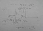
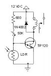
I need to disable some 12VAC garden lights using a relay, when it is daylight. I don't think I need a PIC to do this and suspect it is a simple (for some) job for something like an LDR and an op-amp comparator? Or a photo transistor? to switch the relay. But it would need to be trimmable to set the level of daylight where the relay cuts out.

Any suggestions? I would crack open a garden light but I don't have one and I'd quite like to roll my own for the hell of it.

TIA,
JohnO

[EDIT] I guess the comparator is overkill and the LDR and a trimmer could be a simple voltage divider to turn on a transistor?
 
Last edited:

Jeremy Leach

Senior Member
Well a picaxe solution would give you good control - you could even do some averaging of the light level to make sure it's daylight before turning off, and so avoid false triggers.

Have you looked at Picaxe Manual 3 - Page 28 LDR, Page 7 Relay ? You would need a suitable relay of course. You would read the LDR output directly into a picaxe ADC input. Then your comparing would be done in code.
 

moxhamj

New Member
Re " I guess the comparator is overkill and the LDR and a trimmer could be a simple voltage divider to turn on a transistor?"

You do need some sort of hysteresis though, ie when it turns on it stays on definitely. Otherwise the relay would chatter for a while at sunup and sunset. There are comparator circuits that latch due to positive feedback (schmitt triggers). But I think this would be a perfect picaxe circuit, mainly because it is already in the manual (see Jeremy's link). So you can get all the info for the circuit all in one place.
 

Dippy

Moderator
Hysteresis is an abs necessity to prevent dithering.

This can be done with a comparator. I found a dual comparator (8 pin) and an extra resistor was easy. Maybe a single can do it, I haven't really thought about it.

Its possible with a couple of transistors but a chip will impress other people :)

"I'd quite like to roll my own for the hell of it."
- yes, that sounds good.
Mind you, if everyone else is designing the circuit for you then it sounds more like we're rolling one for you ;)
 

BeanieBots

Moderator
Only one comparitor is required.
However, you do need a reference to compare to.
By the time you've done the comparitor, devised a reference voltage, added the essential hysterisis, then changed your mind about the trip point and how much hysterisis to have, a simple PICAXE 08 solution looks much more favourable.
It also gives added flexibility such as "don't come on until 1 hour after sunset".
 

hippy

Technical Support
Staff member
PICAXE or op-amp / comparator ...

They'll probably both come in an 8-pin DIP so no footprint / size advantage.

The PICAXE solution will need just one R for the LDR pull-up/pull-down, the op-amp will be more complicated needing a pot to set switching level or having to calculate / experiment with fixed R values. Not needing a pot makes it a bit more resistant to corrosion.

The PICAXE will be far more configurable, able to detect brief periods of darkness without thinking it is night time ( overcast days, shadows ) the LDR switching point can be adjusted purely in software and hysteresis can be easily added. Maximum on times etc are simply 'extra code'. You can even have it behave differently on each day if you wish.

The PICAXE may be a little more expensive in real terms but that is offset by simplicity of circuit, the ease of getting the project working and time involved; it can be up and running while thinking about which op-amp/comparator, which component values to use.

The advantage an op-amp/comparator has is that it may be possible to use a simpler power supply, though a 7805 regulator isn't that complicated in itself.


The PICAXE may seem to be overkill for the task but IMO these types of things are what PICAXE's are excellent for. To me it's really a matter of whether one wants the project done and dusted, in the garden and forgotten about and on to the next project or want to spend time and effort finding an alternative solution. Fixed hardware has fixed operation, as soon as you add some intelligence you have flexibility to fairly easily change things.
 

krypton_john

Senior Member
Thanks very much guys.

I think I will 'roll my own' first just for fun and then re-do the job with an 08M. As pointed out there are some rather useful advantages and the component count goes down!

Cheers,
JohnO
 

moxhamj

New Member
Re "I think I will 'roll my own' first just for fun..." - have a look for the schematic for an op amp schmitt trigger. It uses two resistors and has +ve feedback to the positive terminal so it flips one way then the other. What resistors will you use? What ratio will you use? Will you need the two resistors forming the schmitt trigger to be a much greater value than the resistor in series with the LDR, so as to reduce loading the LDR and altering the set points? All answerable with some experiments, though it might get tricky if you find the dark resistance is 1meg (will you be testing it in full moonlight?). If you get loading due to poor impedence matching, you might need a voltage follower. So that will be a second op amp.

10 years ago I would have gone for op-amps, but now I'd definitely build this with a picaxe.
 

Dippy

Moderator
I too would use an 08M.

You could have a simple 'training routine' so you would have to mess about with trying-it-in-situ and then twiddling numbers and reprogramming.
 

Tim036

Member
Thanks very much guys.

I think I will 'roll my own' first just for fun and then re-do the job with an 08M. As pointed out there are some rather useful advantages and the component count goes down!

Cheers,
JohnO
I have a complete proven solution using two transistors driving a relay that has been working a dream for several years.

Complete with pcb.

Any one who is interested I can send a jpg of the circuit diagram.

:)

Tim
 
Last edited:

Dippy

Moderator
When you hit 'Post Reply' look below text box and you'll see a button marked 'Manage Attachments'. Its about 6 inches down from here...

It doesn't contact Anne Summers but it will allow you to upload images.
 

Tim036

Member
R4 is 20k not 47k

Note R2 provides hysteresis to prevent relay chatter.

The sensor is a normal LDR

It is using the non linear characteristics of the transistors.

It also works.

Any queries, ask away.

:)

Tim
 

Attachments

Last edited:

gengis

New Member
Schematic

My light control for an LED array. Dawn to dusk.

The TIP will work in its linear range, since there's no Schmidt trigger, but with the 100 ma the relay needs the worst case dissipation is only 1/2 watt. The relay itself provides plenty of hysteresis for the load side of the circuit.

Nothing is critical. The 680 is there to limit current to the transistor base to a safe level. The LDR is a junkbox part with about 2K to 500 K light to dark resistance.
 

Attachments

Top