marcos.placona
Senior Member
Hello guys, I've recently purchased an 8x2 LCD, and am having a hard time about how to actually connect it to a breadboard for example.
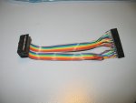
The 16x2 I have is straightforward as it has it's connections all inline. But the 8x2 has connections like this:

As you can see, it has two lines of connections, and if I for example solder a moles (pin headers) to it, I can't plug it to the breadboard because of the spacing.
I've seen a post from eclectic here where he actually managed to do that (on a 40x2 but with the same connection type). I've contacted him, but didn't really understand how he's doing it.
I don't have code problems at all with this LCD, as it uses HD44780 chip which is pretty straightforward.
I just don't know how to connect it. I thought about using some IDC socket connectors with ribbon cable, but then I fall into the same problem again when it's to be connected on the other end.
Even if I solder it to a strip-board, I'll have short-circuits. Eclectic then gave me the idea of using a sharp knife to break the line on the strip-board very carefully. That can be an idea, but I wanted to make sure there's nothing else I should consider before doing that.
Any help would be highly appreciated. Thanks in advance.
The 16x2 I have is straightforward as it has it's connections all inline. But the 8x2 has connections like this:
As you can see, it has two lines of connections, and if I for example solder a moles (pin headers) to it, I can't plug it to the breadboard because of the spacing.
I've seen a post from eclectic here where he actually managed to do that (on a 40x2 but with the same connection type). I've contacted him, but didn't really understand how he's doing it.
I don't have code problems at all with this LCD, as it uses HD44780 chip which is pretty straightforward.
I just don't know how to connect it. I thought about using some IDC socket connectors with ribbon cable, but then I fall into the same problem again when it's to be connected on the other end.
Even if I solder it to a strip-board, I'll have short-circuits. Eclectic then gave me the idea of using a sharp knife to break the line on the strip-board very carefully. That can be an idea, but I wanted to make sure there's nothing else I should consider before doing that.
Any help would be highly appreciated. Thanks in advance.