novice 'old boy' at electronics

olden

Member
Hi everyone.
I'm just learning electronics, (series/parallel resistors stage), and I'm trying different ways to learn as I'm completely on my own. I've got the 'PICAXE'-28X1 as it looks like another learning tool that might help. I've briefly looked at the starter pack and its made me want to get going. C:rolleyes:an anyone with experience tell me that I am going too fast and need to learn more of the basics, (which I'm doing anyway), before using picaxe, or would picaxe use help me a lot better now. I don't want to snow myself under with too much and too quick. I'd be grateful for any advice. Thank you. http://www.picaxeforum.co.uk/images/smilies/rolleyes.gif
:rolleyes:
 

geoff07

Senior Member
My advice is to buy the green book advertised by Rev-ed. This will teach you picaxe and basic electronics, and give you examples that 'just work'. It will also help you appreciate just what else you need to learn. I would also buy some of the small kits (I use the 08 proto board a lot for trying simple things out) and some 08M controllers. As long as you have a suitable soldering iron you could make some interesting things quite easily. Once you need more bits and pieces, you might also try your nearest Maplin shop or online. You will soon figure out what to do next.
 

staylo

New Member
I second the recommendation for the big green PICAXE book. Excellent range of examples and a good reference, though it's becoming a little outdated (impossible to keep pace with the constant updates to the PICAXE range, I guess) the basics stay the same.

For sourcing getting-started components I was about to recommend fastcomponents.co.uk , who had a fantastic range of basic components such as resistor and capacitor kits, neatly labelled in plastic bags at low prices. Unfortunately they don't seem to be selling these any more! Hopefully that's just temporary. I find their breadboards with 50 generously sized jumper cables are very useful for prototyping though.
 

hippy

Ex-Staff (retired)
There are two sides to electronic "analogue" and "digital" and they of course invariably meet along the way. How knowledgeable you need to be about electronics depends on what you want to do and where your interests lie. As with most things, the more you do and read the more you learn and you may find yourself an expert with what feels like very little effort if you have the aptitude for it.

I do mainly digital electronics and beyond the basics I know very little analogue electronics and that hasn't usually held me back. Understanding resistors, ohms law (V=IR) plus power (P=IV), how to calculate resistances and capacitances in series and in parallel, and ( ignore the pedants here ! ) that a high voltage on a transistor base reduces the resistance between emitter and collector has got me by. I do actually know a bit more than that from things I've picked up over the years but that's the basics and you don't need to know much more when starting out.

You cannot beat doing it. A PICAXE flashing a LED on and off and changing the rate it flashes is at will bring incredible confidence and help understanding. Taking a LED and a variable resistor and adjusting its brightness is equally enlightening in purely analogue terms.

I don't think anyone can say you're going too fast or will snow yourself under. If you start 'simple', observe what happens and consider how things would differ if you changed something ( or even put it to the test ) then you'll be on the fast-track to success. You seem to be on the right path already and there are plenty of people here who will help dig you out of the holes and point you in the right direction if you do start to get stuck or feel you need advice.

Having a goal to work towards is I think always a good idea, choosing a small project which you can make work will help you learn a lot. My first project was a night light which turned a bulb on ( a LED is easier these days ) when it got dark using a Light Dependant Resistor which got me hooked. Once you've got one thing working you'll probably want to try something else ... welcome to the wonderful world of electronics and PICAXE's.
 

BeanieBots

Moderator
Only you know the pace you can learn at.
It does not need to be too daunting if you stick to the basics and don't go faster than you can absorb. You can't beat hands on.
I'm more biased to the analogue side for which you will need a strong mathematical skill set if you want to get into complex designs but again, there are ways to avoid needing to do the sums by using chips which do a lot of the hard work for you such as op-amps.
One of the frustrations most newbies have is not enough components.
Get yourself some "bargain packs" of resistors and capacitors so that when sombody says "change R3 to 10k" or "try adding 10uF" you can do it without having to order a part and waiting for it to arrive.
Also, remember that electronic components are not perfect. Capacitors have a certain amount of resistance and the capacitance can change with frequency which is why power supplies will often be seen with maybe 10uF + 0.1uF and 0.01uF on them. When I first started it took me a while to get my head around why anyone wanted to make their 'smoothing' cap 10.11uF when the 10uF was +/- 10%:confused:

Don't forget. We're here to help. If you are not sure, ask.
No question is too dumb. We all started as newbies.

Oh, and to keep Stan (AKA Manuka) happy. Get yourself some breadboard for building prototypes. It's a very quick and easy way to throw together an idea without having to dig out the soldering iron.
 

Dippy

Moderator
Yes, remember Stan does a daily 'search' on the word breadboard to make sure we're all using them.
I just have Stan btw. Be proud.
 

olden

Member
novice 'old boy' in electronics

Thanks everyone, I seem to be going in the right direction. What I have got so far is;
Protobloc 2c board, decent iron, starter packs of capacitors & resistors, digital multimeter, and some basic tools. A project I start (and failed) I purchased LED's, 4049UB, 1N4148, 1N4001 and PCB board.
Maths is my weak point but I'll persevere to try and understand the theory (my brain hurts).
I'll take your suggestion of buying the Green book as that will help and controllers 08, 08M.
Down side, since the original message I thought I would carry on 'getting started' - 'testing the system' and came up with a problem on the simple job.
I noted the numbers 0 to 7 on one side of the IC next to a row of 20 pins. The little bit I've learnt about ic's the numbers run, in this case, 0 - 9 down one side and 0 - 18 on the other. I don't want to spoil my 'PICAXE 28' from the start.
 

Rickharris

Senior Member
Picaxe renumber the pins - They refer to the actual IC connections as Legs and number as you say top left round where the notch signifies the top.

The pins will be different and you need to look them up in the PDF manual. generally they are split into 3 - Inputs, signals that go INTO the IC - Outputs signals that come OUT of the IC (these are just on or off signals (digital)).

and Analogue inputs - these can measure continuously changing signals that can have a value anywhere between full on (supply) and full off, (zero volts) - because the PIC chip only works in digital numbers it converts the analogue signal into a digital number between 0 (zero volts) and 255( supply volts for the picaxe).

So if you have a supply of 5 volts and apply 2.5 to the analogue input and use the command READADC B1 - you will find the value 127 in B1 - ie. half of 255 (rounded up).

The change of numbering is because of internal construction and an attempt to make it easier to understand fr the educational world!
 

hippy

Ex-Staff (retired)
IC numbering is, with the notch at the top, Leg 1 at top left, incrementing downwards, then incrementing upwards along the other side, so for the 28X1, Leg 1 top left, Leg 28 top right.

One confusing thing with PICAXE is "Pin" and "Leg". A "Pin" is a software entity which can be controlled and that is mapped to or from a physical "Leg".
 

Rickharris

Senior Member
Whilst we are at this young fellow, (same age as me - never too old to learn!), I teach electronics and Systems and Control at Boston Lincs, if you PM me an Email address I will send you some of the teaching materials we give out to the students - it may help you along a bit.

I can't load up the PDF files here as they are too big.
 

geoff07

Senior Member
You won't need much maths! Just a few simple equations:

Ohms Law (to work out current, voltage, and resistance):
V = IR

series and parallel components:
R=R1 + R2
1/R = 1/R1 + 1/R2

Power:
Watts = volts x amps

Anything more complicated and there is probably a web page out there to do it for you. Perhaps even for these simple calcs as well.

(I just checked the last point and came up with many pages including this: http://ourworld.compuserve.com/homepages/Bill_Bowden/homepage.htm#menu
quite a few useful gizmos here including most of the calcs mentioned)
 

hippy

Ex-Staff (retired)
One useful thing to know is that a capacitor charged through a resistor will reach its fully charged voltage at some time 't' after charge is first applied. Likewise when discharging.

By using the rising voltage across the capacitor to trigger something else delays can be created and also short or small pulses can be filtered out. Knowing the maths isn't too important, it can always be looked up.
 

Dippy

Moderator
1. In most circumstances (why not all? Test Question1) you will need a resistor in series with your LED. (What value of R? Test Question2)

2. When you get a bit more daring and do your own design please read component Data Sheets. :)
 
Last edited:

manuka

Senior Member
Olden: Class of '48? M8 -you're younger than me(!), so hence the "txt" teaser. I strongly recommend almost all PICAXE dabbling starts with the baby (but powerful) 08M. You'll learn more in ½ hour with these than you'd credit, especially via a solderless breadboard. The 28 & 40 pin PICAXEs can look pretty intimidating for a novice, even though they too are easy to drive once you know how.

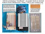
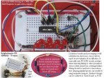
As has been endlessly mentioned before, solderless breadboards are cheap, quick & versatile. Downunder here in Oz/NZ We recommend a layout in the style shown- the little jumper leads speed things up even more while learning, although final designs should use neater wiring. Many resources based around this approach are shown at => www.picaxe.orcon.net.nz, although some initial ideas date back to 2002 & are hence now historic. Stan

Dippy- it's your name I daily scan for in fact!
 

Attachments

olden

Member
novice 'old boy' in electronics

Thanks for the info I thought I was getting confused but I was right about legs/pins. But the main problem is the attachment of the LED and resistor in series, but where? do I solder them to the solder side of the board? it seems a bit messy. Or do I solder to one of the 'blank pins' next to the IC, if so to which pin because I don't know where they are connected. there are three groups of 'blank pins' on the board but I don't know what they're for.
 

eclectic

Moderator
If in doubt; don't!

Olden.

Please DO NOT solder. Yet.
The 28 protoboard is an excellent piece of kit, but needs careful handling.

Get the 08 boards and the rest of the bits, suggested in the above posts.
and play first.

e.
 

Dippy

Moderator
Do you have the AXE020 28 pin project board?
Have you printed out the AXE020 Data Sheet?

Look at Page 3 where it decribes the digital 'outputs'.
Ideally, you would have a DIL socket + ribbon to take the outputs to a breadboard, similar to the picture posted by Stan which is also on his bedroom wall :) Then you can play without soldering. Saves hassle and saves the board.

Look closely at the row of pins aligned vertically. Take a close look , for example, at the second row down marked 'Out 7' this is connected to the ULN2803.

Assuming you have the ULN2803 in place then you would connect between +V supply (which is the pin right next to it), then have a resistor e.g. 1k0, then your LED+leg, then LED-leg to 'Out 7'.
On most non-IR LEDs the long leg is the +ve side. But do check.

I know this sounds a bit silly but the ULN is like a switch-to-ground (a sink, or a low-sided-switch). In fact the opposite of a domestic light switch.

When you code High 7 it will make PICAXE 7 high and in turn make the ULN 'Out 7' a ground - well near as damnit.

See the bottom of page 2 how M is connected. Its a bit like that.
I just wish the Data Sheet showed a few more examples.

Must go, me baths getting cold.
 

olden

Member
Do you have the AXE020 28 pin project board?
Have you printed out the AXE020 Data Sheet?

Look at Page 3 where it decribes the digital 'outputs'.
Ideally, you would have a DIL socket + ribbon to take the outputs to a breadboard, similar to the picture posted by Stan which is also on his bedroom wall :) Then you can play without soldering. Saves hassle and saves the board.

Look closely at the row of pins aligned vertically. Take a close look , for example, at the second row down marked 'Out 7' this is connected to the ULN2803.

Assuming you have the ULN2803 in place then you would connect between +V supply (which is the pin right next to it), then have a resistor e.g. 1k0, then your LED+leg, then LED-leg to 'Out 7'.
On most non-IR LEDs the long leg is the +ve side. But do check.

I know this sounds a bit silly but the ULN is like a switch-to-ground (a sink, or a low-sided-switch). In fact the opposite of a domestic light switch.

When you code High 7 it will make PICAXE 7 high and in turn make the ULN 'Out 7' a ground - well near as damnit.

See the bottom of page 2 how M is connected. Its a bit like that.
I just wish the Data Sheet showed a few more examples.

Must go, me baths getting cold.
I tried to down load but I got the reply 'can't download' or something of that nature (bloody computers)
 

olden

Member
I tried to down load but I got the reply 'can't download' or something of that nature (bloody computers)
Something else I don't recognise:the starter kit came with '2x 10 ribbon cable & 1x 6ribbon cable all with grey sockets on the end. Not mentioned at all to explain where & how they are connected. There seems to be a lack of instructions for novices like me.
 

hippy

Ex-Staff (retired)
I'm not sure which kit you have but you will probably find sockets on the board which those supplied cables plug into.

If they have sockets at both ends they are designed so you can connect the starter kit to your own boards with a similar socket fitted, or they can be cut in half to give two socket to bare-end connections which can be soldered to other boards or with a bit of stripping, tinning and fiddling plugged into breadboard.

What comes out to each wire will depend on what socket it plugs into, and that depends on the starter kit you have. There should be some indication in the starter kit documentation, but it's also possible they are provided as "you may want to use these one day" freebies with no particular purpose expected.
 

olden

Member
I'm not sure which kit you have but you will probably find sockets on the board which those supplied cables plug into.

If they have sockets at both ends they are designed so you can connect the starter kit to your own boards with a similar socket fitted, or they can be cut in half to give two socket to bare-end connections which can be soldered to other boards or with a bit of stripping, tinning and fiddling plugged into breadboard.

What comes out to each wire will depend on what socket it plugs into, and that depends on the starter kit you have. There should be some indication in the starter kit documentation, but it's also possible they are provided as "you may want to use these one day" freebies with no particular purpose expected.
You've solved one problem, I put put them away because the list that can with the starter kit mentioned listed the ribbons but thats all. I have copper striped PCB but there no mention of how it is attached to the board.
The solved problem you gave me was on the 'PICAXE28' board is the 2x 10 pin & 2x5 pin is for connecting the 'sockets' from one end of the ribbon strip.
I've ordered the 'green book' and see if that helps because I cannot download
data sheets or anything else that you need acrobat reader. I don't understand this because it works erery where else.
 
Top