Newbie having problems w axe027 usb cable and downloading

5harkman

New Member
I can’t tell if I’ve done something wrong or if I have a bad cable…

I know there is a lot of info here, but I am trying to be thorough… maybe I missed something simple??

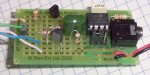
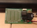
I just purchased and received PICAXE-08 Starter Pack. I’ve soldered it up, loaded the USB drivers, connected the cable and I cannot get PICAXE Editor 6 to recognize my board or even my cable.

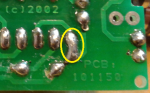
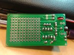
I have searched through the forum and found several similar problems, tried the solutions and tests described with still no luck. In fact I am failing some tests, but not sure what to do or how to fix. Maybe I have a short in my soldering but I think its right measures out correctly.

Ok here some specifics:

My computer: Windows 7 Ultimate 32 bit w SP1, AMD Athlon machine

I am using PICAXE Editor 6.0.6.2 (Beta)
USB drivers :
- AXE027 PICAXE USB (COM5) Revolution Edu, 3/18/2011, V2.8.14.0 with port settings all set to default 9600,N,8,1,None, Latency 16ms, Serial enumerator
- AXE027 PICAXE USB Revolution Edu, 3/18/2011, V2.8.14.0, Load VCP.
Both drivers appear top loading correctly when I pug in the cable with no errors

In the Editor I have typed in the Flashing LED program, although I have not wired any LEDs, just trying to get downloading working and I thought I would get better behavior from the application with something typed in there.

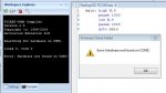
With the AXE027 USB cable connected to the correct USB port on my computer and the other end to my PICAXE starter board, and with 3 brand new AA batteries connected as my power supply, I select “PICAXE” from the top menu of the editor and select “Program/Download” from the ribbon menu. I see the editor indicating it is search for HW on COM5 and within a few seconds I see “Program Failed, Error: Hardware not found on COM5!” popup. I repeated with another set of new batteries, and a different USB port with the same result.

Troubleshooting:
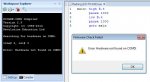
First test is to see if I have communication: I connect the USB cable to the same USB port, connect the other end to my PICAXE starter board, and connect 3 brand new AA battery power supply. In the “Workplace Explorer” on the left panel on the settings tab I have the following selected, PICAXE-08M2, COM5 AXE027 PICAXE USB. I select “Check PICAXE type connected” under “PICAXE Type” and the compiler window pops up with PICAXE-08M2 V2.9, Searching for hardware on COM5. Within a few seconds I get “Firmware Check Failed, Error: Hardware not found on COM5!” popup.

Ok next test…

The following 3 tests are conducted with the cable connected to the computers USB port but not connected to my starter project board.

In the “Workplace Explorer” on the left panel I select “Configure and Test” under the “COM Port” heading” and from here I select “Test Download Cable”
During the first test, the loopback test, I select my cable, COM5, use a paper clip to connect the inner and middle rings of the jack plug and go to the following screen and see absolutely nothing in the window…

The second test is a check for power/voltage on the jack plug. With the cable still plugged into my USB port from the previous test, I remove the paper clip and connect a DVM to the outer and middle rings. No voltage is measured, I see a little oscillation in millivolts which I attributed to noise.

So those 2 tests fail, however I have something working… by accident I had left the jack cable connected to my PICAXE board during the loop back test and I see “Hello, I am your PICAXE-08M2” being repeated pumped out. So there is communication, maybe?

I tried another test.

Leave the cable connected to the USB port and remove the cable from my PICAXE starter board and put the loopback paper clip back in place. Close the “Configure and Test” and “Test Download Cable” windows. In the Editor select PICAXE from the top menu, and then select Terminal from the ribbon menu. Select COM 5, 9600, N, 8, 1, None. Also note : DSR & Break are RED, I assume this off or 0, and CTS, DTR, RTS are all GREEN. With port open, type value in transmit buffer and hit send. I see nothing in the receive buffer. Then I change DTR(Data Terminal Ready) from GREEN to RED by clicking on it. With port open, type value in transmit buffer and hit send. Wala! What I type comes back in the receive buffer.

So I have some sort of communication, but I still cannot download.

Please help.

Thanks!
Mark
 

tony_g

Senior Member
ok im not familiar with most of the boards reve ed sell but i assume this is a self assembly board?

if so do you have a 3pin header jumper that you need to switch for alternating between programming/using the serial pins as g.p inputs/outputs? if that is not in the prog position maybe thats causing the hardware fail.

proto2b.jpg

have you double checked the solder joints for the download socket and resistors.

double check the resistors are in correct position.


tony
 

AndersK

New Member
If not the above suggestion works try and check with a volt meter.

I had similar problem last week. Couldn't find anything wrong when checking resistance but found a problem with the board while looking at voltage drop. Zero resistance but yet a 2 volt drop between two solder points that were supposed to be connected.
 

hippy

Technical Support
Staff member
Welcome to the PICAXE forum Sharkman.

That you can see "Hello, I am your PICAXE-08M2" shows the AXE027 is capable of receiving, and your second test with Terminal to show that it is as capable of transmitting as well.

Why this only seems to work having altered DTR in Terminal will need to be investigated. When the Programming Editor program downloader and cable test programs open the ports they do so with hardware handshaking disabled so this should not affect their ability to either send or receive.

It looks like something is preventing the program downloader and cable test programs from sending to the cable and this means the PICAXE is not responding and firmware checks, download and cable tests fail. It is not clear why that should be and that should not be happening.
 

5harkman

New Member
Thanks AndersK. I checked some voltages from both the component side of the board where I could and the solder side. As best I can tell, things look right. Is there a guide somewhere that shows what voltages should be measured at specific points when the standard 3xAA supply is connected?

Thanks,
Mark
 

5harkman

New Member
Thanks Tony. I think my resistors and jumper are in the correct location. It looks very similar to the picture provided. I snapped 2 myself, front and back.

Front:
PICAXE-08M2 starter board front.jpg

Back:
PICAXE-08M2 starter board back.jpg

As far as double checking the solder joints, I did a continuity test and voltage drop measurement from solder side to top side on both ends of both resistors, all 5 solder joints on the jack, and the supply pin and ground pin of the chip. All checked out.

-mark
 

The bear

Senior Member
@5harkman,
Your soldered joints on the jumper look as if they may be touching.
Myself, to program the picaxe chip, I have to unplug the USB lead, then plug it back in before it can find its COM connection.(Every time I use it, once done its OK).
Win 7 , Editor 6.0.6.0

Regards, Bear..
 

srnet

Senior Member
I had similar problem last week. Couldn't find anything wrong when checking resistance but found a problem with the board while looking at voltage drop. Zero resistance but yet a 2 volt drop between two solder points that were supposed to be connected.
If your measuring it correctly, thats not possible.

You cannot have 2 Volts across a 'Zero' resistance.
 

srnet

Senior Member
True, but did the resistance check without the cable connected. As soon as I connected it I had that voltage drop. Tiny crack I suppose.
So a measurement problem.

You were not actually seeing 2volts across a 'zero' resistance.
 

5harkman

New Member
I checked these 2 pins, thye are tied totogether, 0 resistance, just to make sure, I dropped a piece of tinned wire and added more solder. Nothing changed.
 

5harkman

New Member
Thanks The bear. I removed the jumper and checked for continuity or lack there of. Measures completely open between each of the jumper pins on both sides of the board. I also tried unplugging and replugging the USB cable from the PC, serial jack from the board, and power from the board, trying different order each time. No luck. I'm going to try another suggestion for a different editor next.
 

5harkman

New Member
Thanks Rick100. I tried both V5.5.5 and V5.5.6. Both editors are giving me the same result. Next is to remove all trace of axe027 usb drivers and try reinstalling them. This is tricky, because Windows likes to do you favors and remember stuff. But I have messed with with a few USB drivers in my time, so I am going to give it whirl.

Thanks,
Sharkman
 

5harkman

New Member
cable test where you check for power between the tip and middle ring

The second test is a check for power/voltage on the jack plug. With the cable still plugged into my USB port from the previous test, I remove the paper clip and connect a DVM to the outer and middle rings. No voltage is measured, I see a little oscillation in millivolts which I attributed to noise.
Mark
So I have tried just about everything I can try, even removing and replacing the drivers from my PC with a fresh downloaded version and re-installing. Still can't download, all the same behavior noted previously except as noted... I might have provided bad information or something has changed. In the cable test where you check for power between the tip and middle ring, I may have forgot to click the button in the application widget to get the voltage to 5V. When the button is off, I get the mV oscillation as indicated previously(most likely noise at 0V), when I turn the button to ON(bright green), I see ~0.5V steady. Does this trigger any ideas in anybody's experience?

I am going to try this on another computer tomorrow.

Thanks,
Sharkman
 

MartinM57

Moderator
Despite your experience of USB drivers, have you followed the instructions for the AXE027 drivers EXACTLY I.e to the letter They aren't like normal drivers...make sure you read and follow the instructions :)
 

5harkman

New Member
Thanks MartinM57. I am pretty sure I followed the instructions as close as possible. First installing the drivers, then plugging in the cable and waiting for windows to load drivers, then selecting the AXE027 device, then properties, then driver, and updating USB driver, then closing all windows, then re-selecting device, then properties, then driver, and updating COM driver, then closing all windows. There are steps indicated that are not in my version of windows 7, but I do go through each of these steps as I have indicated. When its completed I have both the USB driver and the COM port driver loaded successfully with no errors. If I unplug the cable the drivers unload, and when I re-plugin the cable they re-load with same COM port, just like every other USB driver would.

Thanks,
Sharkman
 

5harkman

New Member
I must have a faulty cable... only thing I can guess at this point. I even tried on another PC with intel processor/mother board/architecture with the same result. The other PC has a different version on windows 7 and I was able to follow the driver installation instructions exactly, all same windows, etc. Same behavior from the cable and my PICAXE starter board. I am open to more suggestions, thanks for the help all.

Thanks,
Sharkman
 

Rick100

Senior Member
You may have a broken wire in the cable. Check the continuity between the shell of the USB plug and the tip of the 3.5mm plug. If that's ok try the test you did in post 16 while you wiggle the cable. You could also cut off the 3.5 mm connecter and solder another on. I think Radio Shack carries them.

Good luck,
Rick
 

5harkman

New Member
aha, a test that shows the cable is bad, maybe

You may have a broken wire in the cable. Check the continuity between the shell of the USB plug and the tip of the 3.5mm plug. If that's ok try the test you did in post 16 while you wiggle the cable. You could also cut off the 3.5 mm connecter and solder another on. I think Radio Shack carries them.

Good luck,
Rick
Thanks Rick. I did the test for continuity between the shell of the USB plug and each of the 3 points of the 3.5mm jack plug, and it shows no continuity. Does this test work with your cable? I know there are active electronics in the cable, so there could be a capacitor or some other resistance preventing continuity. I measured capacitance from the 3.5mm tip to the USB outer case about 5.3nF and slowly climbing and 5.5M ohms and slowly dropping. I have a small pocket multimeter that has coin sized battery so accuracy for this type of measurement is skeptical at best, but it certainly is not straight through.

Thanks,
Sharkman
 

Rick100

Senior Member
Thanks Rick. I did the test for continuity between the shell of the USB plug and each of the 3 points of the 3.5mm jack plug, and it shows no continuity. Does this test work with your cable?
I'm sorry. I assumed the metal shield was connected to ground. I tried it on my FTDI cable, which is not an axe027, and they were not connected either. Using the pinout here, check from pin 4 to the tip.
http://en.wikipedia.org/wiki/USB
You should have continuity between them. I used a piece of solid wire to reach the contact in the plug. Only the ground connection can be checked for continuity. I would also redo the test in post 16 while you wiggle the cable.
Good luck,
Rick
 

5harkman

New Member
The continuity test from USB pin4 to the tip checked out.

I have tried wiggling both ends of the cable as well bending and unbending the bends in the cable from when it was packaged. I will try again, but I think I am going to try and purchase another cable. I search my personal inventory, and I have other USB to serial and serial to 3.5mm jack cables but to connect the two, I would need a 9 pin gender changer or 9 pin null modem adapter. I can't believe I don't have these. maybe I will get 1 of each.

Thanks so much for the help, but I still can't program my PICAXE.
-Sharkman
 

Rick100

Senior Member
If you think the electronics in the cable are bad, you can cut off the 3.5 mm jack and do the test directly on the wires, unless you intend to return it. Just make sure you unplug the cable before cutting it off so you don't short anything.
Good luck,
Rick
 

5harkman

New Member
Thanks to Rick100 and everyone else that has been helping.

I purchased a new cable and wala! I can pass the cable test. There must be something wrong with my first cable, in the trash it goes, unless someone wants to debug it.

That being said, I am still having a problem with down loading. :(

As I indicated, the cable appears to be working correctly. The paper clip loop back test is providing the loop back text. The cable voltage test is providing 5 volts when the switch is on and 0V when the switch is off.

When I go to the terminal screen with my PICAXE-08 starter board powered up with 3xAA power supply and the jumper in the programming position, I get the "Hello, I am your PICAXE-08M2", message, repeatedly.

However, when I select "Check PICAXE type connected", I get "Error: Can't open COM5" and when I select "Program", I get "Error: Hardware not found on COM5!"

What am I doing wrong?

Thanks,
Sharkman
 

Technical

Technical Support
Staff member
In PE6 select the correct port (not COM5) via the settings tab on the Workspace Explorer. What port is terminal using - also a port can't be used by two things at the same time, so also close terminal /troubleshooting wizard etc?
 

5harkman

New Member
In PE6 select the correct port (not COM5) via the settings tab on the Workspace Explorer...
huh?

My AXE027 is loading on COM5. Under "COM Port" item in the "Settings" tab of the "Workspace Explorer", I have 2 options, "COM1 Communications Port" and "COM5 AXE027 PICAXE USB". With either COM selected and selecting "Check PICAXE type connected" I get, Hardware not found on COMX!.

screen shots:
COM1 Check PICAXE Error Capture.JPG

COM5 Check PICAXE Error Capture.JPG

Looking for troubleshooting guide now, to see if I missed something.

Thanks,
Sharkman
 

Rick100

Senior Member
I was reading through this thread:http://www.picaxeforum.co.uk/showthread.php?25499-Hardware-not-found-error&p=259017&viewfull=1#post259017
It seems one thing that would cause your error is a break in the serin circuit on your board. It's easy to test for. Pull the chip out of it's socket and put a jumper wire between pins 2 and 7 of the socket. Then do the loop back test. Since you got the welcome message before, you know the transmit works. If the loop back test fails it must be the receive circuit that doesn't have continuity. I just tried it on my 08 proto board.

Good luck,
Rick
 

Technical

Technical Support
Staff member
Based on the above observations the problem has to be on the board around the serin pin (as serout is working to transmit the hello message), so we went back to your original photo.

Has anyone yet mentioned the big blob of solder joining two joints that should not be touching each other?

This is shorting your serin pin to 0V, so the PICAXE can never receive any data.

See attached image showing the fault, a clean hot soldering iron run between the joints should separate them.
 

Attachments

5harkman

New Member
Thanks Technical and Rick100! The jumper test, by removing the PICAXE chip and jumping legs 2 and 7 or SerIn to SerOut for the loop back test that Rick had suggested was failing so this lead me to a problem with the board. It took me some doing, but I was able to find the same problem that Technical has pointed out, a solder short between the 2 resistors. I didn't see Technical's response until I logged back in to let you all know I found and fixed the problem. I successfully downloaded the flashing LED program into PICAXE. Yahoo, now I am off to the races. :)

Thanks for all the help for everyone who chimed in with comments and troubleshooting ideas, it all lead to finding the problem.

Just out of curiosity, I went and pulled the old cable out of the trash and it still does not work, so back in the trash.

To summarize, I had 2 problems preventing the system form working properly which compounded my initial debug. First the AXE027 cable was bad. Second the sloppy soldering between the 2 resistors effectively shorting SerIn to Gnd/0V.

I must say, if it was not for this problem I would not have understood the circuit as well, so there has been some learning.

Thanks again,
Sharkman
 
Top