New Project involving Xbee modules

manie

Senior Member
Well- that roof cladding looks a tad combustible, but you won't have any trouble with the neighbours! That fence indeed may be a 1mW XBee issue, so 433 MHz could be the answer.
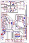
This is the "wet" season, wait till its dry ! Neighbours ? Whats that ? I was told by the manufacturer today that 200m could be expected, at 4800 bd. Now the boards, get it together and test here on this farm first... then off to the site...
Manie
 

manie

Senior Member
Stan: As promissed a pic of the "Strain-fi", just a ZAR 50.00 (Au $+-8.00) strainer type food/cake cover. (Works wll as a sieve too...) As you can see I have just propped it up straight against the window, and yes, outside right in front of it is a lush plant... Signal strength has moved up 1 bar to three bars, and internet connection now happens ONLY on HSDPA, never 3G anymore. It really does work !
Manie
 

Attachments

manie

Senior Member
Modified Circuit

BB:
1. This relates to your earlier comments regarding paralleled 78xx regulators. I monitored (with digital IR spot thermometer) two 7812's paralleled on another circuit and one was indeed warmer than the other.... so it was doing more work. I have now modified the circuit (schematic and layout attached) to include two PNP pass transistors instead. I am using two BD244C's (6 amp PNP) instead of the TIP2955 shown. (TO-220 vs T0-3 package). I will probably never exceed 1 amp current demand on both the 12V regulated feed and the 5V regulated supply. Nonetheless I will fit TO-220 PCB mounted heatsinks to the BD244C's. The schematic and idea is courtesy of : http://www.zen22142.zen.co.uk/Circuits/Power/power.html
2. I have also removed the rather crude N channel mosfet used for level shifting the Serial signal input and have replaced that with a MAX232N serial driver chip. All in all, much neater and much easier...

3. I have also included additional by-pass caps , also one right by the 40x1's power pins.

I have put 4k7 pull down resistors on the gates of the 7 x 2N7000 mosfet switches to ensure the gates are off when the 40x1 outpins are low. Is this OK or even required ?

See, we noobs DO LISTEN (sometimes), in my case its taking a bit longer to get to Stan's "proof of concept" urgings, but don't fret Stan, I WILL do it and post results (good or bad..) so some other noobs can also listen and learn. Personally I think this change is a BIG improvement and much needed for reliable operation.

As always, all comments and guidance gladly accepted.

Manie
 

Attachments

Last edited:

manie

Senior Member
Please refer to the image in the post above. I have wired portc pin4 (leg 23) as the TXdata (from 40x1). After SCOURING the manuals it seems that this cannot be used for SEROUT command, just as an "on/off" pin. The manuals I must say are quite sparse for info on Portc uses, maybe an inclusion of "can do's and CANNOT do's " will help a lot of us.

Can I use Portc pin4 (leg 23) for serout ?? I surely hope so.... The circuit is built and everything checked out very nicely, first try, except for the "Syntax error" on Portc pin4.
Looks like I might have to cut some traces and re-route with wire jumpers ??

Your input/s again appreciated.
Manie
 

papaof2

Senior Member
Most of Port C has limited use - just functions that are basically on/off. (Do a search for Port C to see other posts.)

Picaxe Manual 1, version 6.6.11, section 1, page 8, lists the pin uses of each chip and shows only the following for 40X1 leg 23:
in c4
out c4
i2c sda
spi sdi

If you move to leg 25, you get hserout.

John
 

cvrwy

Member
Ah, Manie.............Is it too late to tell you that you should breadboard your circuit exactly as you determine the circuit will be in its final form? Did I say that correctly? Did I hear it correctly? Obviously not, Manie..........because I have taken your path many times........
 

manie

Senior Member
Papa of 2: Thanks, I worked that out even though hoping that I read the manuals incorrectly.... one never knows with these CLEVER "hippies and dippies" type guys !

..........because I have taken your path many times........
John: Yeah !!! (sigh)... but thats the way I learn more (excuse), fortunately I could cut the affected traces and re-route with wire links, so its still useable !

Now I will NEVER ! Never ! use inputs for anything BUT inputs/digital outputs in my future projects again. Live and learn..
Manie
 

lbenson

Senior Member
Don't say "never"--as 7_of_9, I mean P_of_2 said, there is hserout sitting just two legs up, begging to be used.
 

hippy

Technical Support
Staff member
Now I will NEVER ! Never ! use inputs for anything BUT inputs/digital outputs in my future projects again.
I wouldn't say that too soon considering the forthcoming X2's. If you've read your PICAXE Manual 2 you will see their I/O capability is considerably flexible and could save your bacon without having to cut and dice the PCB.

Part of prototyping is writing some test code as well as getting the hardware proven. A bit of flexibility in I/O assignments can help whoever is doing the PCB tracking, but with PICAXE's one of the 'compromises' for ease of use is slightly more restricted options. Some functions are also tied down to what the underlying PICmicro can support.
 

manie

Senior Member
I don't blame the chip Hippy. I did not understand the manual correctly as it is a little unclear on a moot point. Now I know though ! Ain't that good in itself, you learn from errors... This weekend some code and tests, hopefully with the 433mHz attached ! Take note Stan !
 

manie

Senior Member
I have a problem ! It is called "serin".... what else. Transceivers are setup, that was REAL easy, 10 out of 10 for Nordic and Polygon Technologies... The RF's are both sending and receiving according to the indicator LED's. The 40x1 is transmitting a "for---next" loop, this is received and passed on to the PC and displayed correctly. It then asks for "b1" etc. I use Terminal in PE to send data back but get no further response. Here is my code:
Init:


'set freq to enable 9600bd comms
setfreq m8
pause 2000 'wait 1sec(8mHz)
b1=1
b2=10
goto seroutrf


SerOutRF: 'This part works...
high 0
pause 2
for b0=b1 to b2
serout 0,T9600_8, ("bo=:",#b0,13,10)
next b0
b1=0
b2=0
serout 0,T9600_8, ("Send >b1<",13,10) 'asking for the new loop values here
gosub serinrf 'which I receive OK
goto seroutrf
stop

SerInRF: 'the problem starts here...

do while b1=0 'tried both N/T9600_8, no go, with/without qualifiers,no go
serin 2,N9600_8,("ABC"),b1 'does it hang in this loop ???
loop
serout 0,T9600_8, ("b1=:",#b1,13,10) 'It does not get to HERE or further...
serout 0,T9600_8, ("Send >b2<",13,10)
do while b2=0
serin 2,N9600_8,("ABC"),b2
loop
serout 0,T9600_8, ("b2=:",#b2,13,10)
pause 2000
return
I'm obviously doing something stupid. But where and what ? Can you help, manual-2 does not tell me much or I need shut-eye, its 03H08 AM !!!!
Thanks in advance
Manie
 
Last edited:

lbenson

Senior Member
If you take out the transmitter and receiver and directly wire it, including grounds, does it work? Make sure the code is right for hardwired comms before you put the wireless into the loop.
 

Dippy

Moderator
Life ain't ever easy.
And neither is understanding your layout.

Is your example code just 'one half' of the system?
I see you use "ABC" as qualifiers; so that preamble is sent from t'other end?

Then you say:

"gosub serinrf 'which I receive OK"

and, then at the label you say:

"SerInRF: 'the problem starts here..."

So, are you saying:-
1. That if you run it without your request ("Send >b1<",..) and the other end is just set to transmit in a loop then its fine?
2. As soon as you introduce the request ('handshake') then it stops?
3. Have you checked the other end is getting the request correctly?

I don't know what make or quality of RF modules you are using but do they need a preamble - many basic modules do.

A little system schematic may help others here.

And Ibenson's suggestion is a good one and is the usual 'get-the-serial-side-working-first-before-RFing' method.

Have some kip, then try Ibenson's suggestion.
Persevere dear boy... you'll get it sorted.
Good luck.
 

manie

Senior Member
"I think he's got it..." says Henry Higgins !

Ibenson: Comms both ways is happening fine now, after adding preamble/s there is good bi-directional comms, PC to 40x1 to PC again. Thanks for the suggestion.

Dippy: I had some kip thanks, and how are you this fine morning ?

Here is what is happening as I see it:

I send what I think is the NUMBER 1 upon request for "send b1". The code now (after adding preamble/s) reponds with "b1=49", the ascii value for "1" !!

1. Does this mean I need a ASCII lookup table burried in EEPROM memory ?
2. If I do, what will be the most code/space efficient way to do the lookup/translation ?
3. Or have I got it wrong again ?

The basic setup is just that: quite basic...

40x1==> RF#1......rf DATA.....>> RF#2==> PC (sending loop and request for b1), then in reponse to request,

PC==> RF#2..... rf DATA.....>> RF#1==> 40x1 (sending the requested value for b1).

Does this help ?
Manie
 

Dippy

Moderator
I bet you are sending #b1.
# means convert to ASCII - and is usually only used for displaying things.
Effectively it just adds 48 (for a single digit). ASCII 48 is the 'printable' value of 0 (zero). 1+48=....

Save your '#' for sending to terminal and other serial display devices.
Knock it off and try again.

PS. Check 'Serout' in the BASIC Manual. Page 158 about halfway down.
 
Last edited:

manie

Senior Member
Dippy: I send b1 from within the Terminal window in the Pr. Editor... does that add the "#" ? I just type the NUMBER 1, no #'s or anything. I tried sending %00000001, but that did not work either. I have a laptop without number keypad, could that be it ? (don't think so though as numbers work in other programs..)
Manie

Edit: I have setup the transmitters to send each byte as received, there is an option to wait for a "packet" (32 bytes) or to time out and send the current "packet". Which would you think best ?
Problem is sending the number "20"(no quotes) will send two bytes, first "2" then "0" the way its setup now(single characters). Packet sending is probably best ?
Manie
 
Last edited:

Dippy

Moderator
Dunno about the packet, but anything you send from terminal will be the ASCII so sending
20<return/enter> will send ASCII"2" & ASCII"0" i.e. 50 followed by 48.
(All the terminal things I use have an option whether or not to send a terminator)

I don't know if there are terminal packages that can send , in this example, 20 as a byte.
I haven't looked as I usually either knock up a VB prog or use PIC to PIC for testing comms.

Alternatively, and what i do sometimes, is use a letter character for a command. (assuming the numeric value isn't important e.g. being used for a calculation).
 

manie

Senior Member
I've downloaded AiTerm V6.??? and it is doing the same as Terminal. It can be set to send char by char or a whole line. The receiving variable just gets the 1st value, eg. send ABC123 (qualifier/value), the byte received is 1(displayed as "b1=: ",b1) or shows 49 (displayed as #b1). How do you get a a real world number such as 123 or 999 for calc's etc into your variables, other than resorting to VB MScomm stories ?? The transmission up/down both ways is fine now except for this value sent problem.

Anyone ?? Help ??
Manie
 

hippy

Technical Support
Staff member
For AiTerm, to send a byte value ...

1) Get to the menu bar. Press the small button left of Clear and Copy buttons if in Frames mode.

2) Ensure Transmit -> Send Whole Lines is ticked

3) Ensure Transmit -> Send Character Codes is ticked

4) In the bottom text field, enter 123 ( no quotes, do not press return ).

5) Press the "#" button to its right ( do not press return, do not press the Send button ).

This will send a single byte of value 123 / $7B / "{"

If you wanted to send "ABC" then a single byte, enter ( including the quotes ) ...

"ABC" 123

Then press the "#" button. If you tick Display -> Local Echo you can see what is being sent,

If your PICAXE program were SERIN...("ABC"),b0 then b0 should end up with the value 123 in it.
 
Last edited:

manie

Senior Member
Hippy: Your pages might be happy but SO AM I !!! Thanks mate, that did exactly the trick required. With the two transceivers about 4 inches apart (no antenna's fitted yet, just the soldering pads...), comms both ways are excellent and fast. I currently run the chip at 8mHz and baud rate at 9600. I'll do a range check at that baud rate, and slow things down as required if the range/baud rate seems to require lower speeds. This is a controller for a "Chook-House" (as per Stan), so there will be no great hurry to get the data across. Possibly once a minute maybe even longer periods between or even just on alarms being triggered, so I can quite easily go down to 1200bd to assist in getting more range. Then there is Stan's "Wokfi" still....

Thanks all, the comms is up and going due to your direct input. It is APPRECIATED !
Manie
 

hippy

Technical Support
Staff member
Glad it's working.

There's probably little need to worry about baud rates, the XBee communicate with each other at a high-speed baud rate regardless of that used for the local PICAXE to XBee connection. In fact you can have one side of the link using 9600 or faster, the other end 300 baud if you want.

Unlike 433MHz, you won't get any benefits from dropping baud rate, no improved reliability nor improved range. With XBee, like a postal service once you drop your letter off, it's out of your hands how and how fast it gets to where it's going. Stan's Wok-Fi and directional aerials are the best you have to improve reception and range.
 

manie

Senior Member
Hippy: You might have missed the post where I said I've changed to 433mHz from Polygon Technologies. Beautiful little modules based one of the Nordic chips (xx905 I think). The (almost) half-wave antenna is 170mm long. It might just fit inside my "Strain-fi" after Stans Wok-fi. (see a couple of post ago..)

I decided on 433mHz after Stans insistant pleading that 2.4GHz will have problems with the security fences etc. The three Xbee's that I have is now available for another future project I will think of.... must get this controller complete and installed in the chook-house to take care of the menial temperature/curtain control.

The next challenge in this saga is to get decent 12Vdc geared motors that are both SMALL enough and with ENOUGH TORQUE to raise/lower the curtains(one-piece-canvas hung horizontal and 30m long !) They operate by hand on a little drum winch. I have an idea as to the final SLOW and HIGH resolution up/down control. I will monitor curtain position by Hall-Effect switches...

thanks so far to all..
manie
 

Dippy

Moderator
I am pleased you've got it working. Phew!

I just hope that it doesn't take another 6 weeks to make a motor turn :)
 

manie

Senior Member
Dippy:
I just hope that it doesn't take another 6 weeks to make a motor turn
Dippy,Dippy,Dippieeeee ! So do I though. I'm splitting time viciously between various other things, I was actually a bit scared off to tackle this RF comms thing, but now.....

Have installed a DS18B20 temp sensor. Code is working as I want to (no MOTORS Dippy) with LED's as indicators. Marvellous thing this "Readtemp" command, SO EASY ! Thanks Rev-ED, thats a good one on your chip ! The chip drives 2n7000 mosfets acting as on-board output switches. Its all comming together well now.

At least I know now the controller will work locally, the RF range thing will be one of the next issues. Will post a pic of the bench test setup (maybe, there are so many cables and loose wires...).
Manie
 

manuka

Senior Member
Manie -pleasing to learn of progress. "WokFi" approaches are indeed suited for 2.4GHz, where a wavelength is only ~125mm, BUT will probably be quite useless at 433 MHz- where wavelengths are ~700mm. UHF Yagi's should be explored instead. Stan
 

manie

Senior Member
Very crude setup used to prop and balance 1/2 wave antennas and tried range test between the Polygon 10mW transceievers. Got to 57 meters with good transfer, at 58 meters, sudden dropping of bytes... at +- 60 meters, no contact.

I must add however, there was very little "clear" air around both antennas. One on top of the car roof, the other on a kitchen tray carried by my wife at waist height, so hardly a fair "trial".... Both antennas propped and balanced precariously under quite unfavourable conditions..

Nonetheless, I'm now constructing a "Cotanga" 4 element Yagi, supposed to give you 7db gain, which should improve rnge quite a bit...

Will keep you posted as to progress.

Manie
 

manuka

Senior Member
Manie: OK-this is the sort of wireless finding to check FIRST of course... Try elevation above metallic objects? 6dB will double range, so a ~6dB (after cable losses) "cotanga" at each end will give ~x4 your raw range. This may be just enough, but electric fences etc may still cause drop outs & data corruption. Surely a case of YMMV...
 

manie

Senior Member
Stan: I hear you and I DO listen..... sort of.... This project started as a temperature/humidity/alarm controller idea, so if that works, fine. The Rf comms I added as a "required" and very nice to have, so it is almost essential. However, I was doubting that I would get a range ANY further than 30m MAX ! So almost double that on first try to me is very encouraging ! Hence my attempt now at the "cotanga" yagi, I will elevate both antennas to AT LEAST 3m above ground to give it "best' chance. I'm sure range must improve then by a good factor. If I can get to 100m here (home) on the farm, then I should be OK at the actual site too. I have both trees and electric fence here as well, so if I clear that it will work on site as per the picture posted earlier. This is all a "trial and error" excercise to me, what I learn now will always assist me in future. Between you guys urging and me trying it will be OK I'm sure.

PS: "YMMV" ???
Manie
 

manuka

Senior Member
YMMV = "Your Mileage May Vary". In the circumstances it's meant as a pun- perhaps hence it should be => Your "Metre"age May Vary ...

Extra: Unless a metal wall was in the propagation path, this sudden drop out at a mere 60m seems to contradict my experiences. Are you sure #1 wife didn't just stash the tray in the car & go shopping while she had a clear run away from the house?! Even the Jaycar Keymark's (costing ~ US$5 each) will do better than this LOS.
 
Last edited:

Dippy

Moderator
433 & 10mW 60 metres?
Oh dear, something wrong there.
What baud rate?
Any encoding?

I don't understand "...there was very little "clear" air around both antennas. One on top of the car roof...".

Do you mean just plonked on top vertically?
Did you repeat experiment with the antenna well away from metal?
Was the car roof a pukka ground plane?

I was getting 500m reliably at 2400 baud with no Manchester or similar and no ground plane with some RF Solutions modules and 1/4w whips.
And that had bushes and my Mother In Law in between.

Have you got your antennas chopped to the right length or did you buy proper ones?
Is your connection from RF Module to antenna nasty? (e.g. poor matching)
And you haven't got the antenna 'hot end' near metal?
Are you sure you have 10mW?

Finally, have you checked RSSI with no transmission to see if there is much nasty background RFs/Noise.
If you haven't got RSSI can you measure data out pin.
This is where a 'scope can be REALLY handy.

Or, it is obviously possible that you have a duff RF module. Did you buy a spare?
 

manuka

Senior Member
Dippy & Manie- as I'd earlier pondered (way back in Post #67 !),specs. for these Polygon units imply they're a tad deaf, & hence (in spite of their high price) they may not be able to "cut the mustard".

Manie - I STRONGLY SUGGEST YOU DO A SIGNAL COVERAGE/SITE SURVEY & INTERFERENCE CHECK- use some dead simple 433 MHZ gear. I could easily have posted you a Jaycar "Keymark" matched pair over 2 months ago! Given the time we've all put into helping you with this quest, I'd say I'm not the only one who feels it's been an unproductive quest ...
 

Dippy

Moderator
I only dipped in an out of this thread so didn't read all your replies Stan.
I timed-out....

I'd forgotten the module Manie was using. I have no experience of it or even heard of the brand. But as it 'does all the stuff' onboard then your testing is limited.

I just had a quick look at http://www.pteq.net/downloads/files/RS232-RFmanual1.23.pdf
Is that the one?

I couldn't see sensitivity figure for Rx, but with a claimed 300m LOS (assuming whip/helical no-gain antenna) I would have thought that you should be able to get half that if you haven't made a booboo.
I'd also try it with a ground pane.
I don't know how fussy the module to antenna conenction is or even if manie has made it properly.

Yes, I would also ordered some cheap 433 Modules to check background.

But as SO much of this is down to manie's construction skill then I'll leave you to it.
ALL I can suggest is look at Data Sheets from people like Radiometrix and RF Solutions to get hints and tips on antenna contruction, connections and how to run PCB tracks.

Good luck. See you in a month time ;)
 

manie

Senior Member
Stan: Unproductive NO NO NO !!!!

I've learnt something (at least) on RF. I've progressed from zero to first transmission, actual data being sent, I've implemented this on a 40x1 chip, I've made a reasonably good looking PCB, I've sorted out the level shifting (TTL-3,3V) with Max232N, I've tried LED display and finally went for LCD with Firmware and now I've built two "Cotanga" Yagi's, and ALL this with the help of the people I got to know on this forum ! For all that help and "watch-outs" I once again say a GREAT BIG THANK YOU.

CERTAINLY NOT UNPRODUCTIVE !

You guys have helped me come a VERY LONG way... I'm absolutely sure I would not have been anywhere near this stage by myself, so please Stan, a pat on your shoulders for all that.... just look at what I've learnt. If the Polygon Tec units are not up to it, well then I'll have to take you up on the Jaycar offer and try again.
As far as connecting the antennas to the units are concerned, see pic attached for close-up detail. If its not right, then please tell me whats wrong. The antennas are units bought straight from Polygon so I imagine they should be the real Macoy ??

I'm attaching pics of Yagi's also, built on 50mm PVC drain pipe for easy transport and field work. The actual elements are stiff 2mm baling wire, maybe the aspect ration is a bit off ? Picture of antenna attchment to RF unit also attached.
Yagi pic in next post.

Please let me know...
Manie
 

Attachments

manie

Senior Member
Ibenson: Please LURK ! Thats what this forum is for. Hopefully this project will be "broadband", that is, include many aspects of the Picaxe and its applications, this one in particular for full-house environment control, eventually (sooner rather than later) with CO2/CO/Humidity/Windspeed/Wind direction/Shutter controls/Alarms (various levels)/two way RF Rs232 with parameter updating from PC/data storage, analysis on PC/remote data data display(PC)/local data display(LCD) etc. etc. It certainly is growing and I am learning a lot despite Stan's concerns for which I am gratefull !!
manie

Edit 2: The project will be complete when I have created a full MS Access Database with code (and screens/forms) to control alarms/monitoring parameters and the like. Proper databasing of the raw data for proper interpretation and display must be added.
 
Last edited:

eclectic

Moderator
@manie
re. your posts #116/117
“I'm attaching pics of Yagi's also, built on 50mm PVC drain pipe for easy transport and field work.
The actual elements are stiff 2mm baling wire, maybe the aspect ration is a bit off ? “

I'm assuming, from the ground up
reflector / driven / d1 /d2

I can't measure it properly, but, it just doesn't look right.
The d2 looks too long.

See, for example
http://www.picaxe.orconhosting.net.nz/yagi433.jpg

Secondly, what will you use for the feeder cable?
As in RG58 / RG174 .........

e
 
Top