'New' 28X2 - 64 Mhz at 5v - is this real ?

PowerSpike

New Member
I've repeated the test using a fresh 16Mhz Resonator and a breadboard (no cooking of the components).

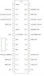
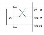
Minimum circuit with no complications:

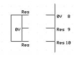
Resonator connected to legs 8,9 and 10
Ground connected to legs 8 and 19
+5V regulated connected to Leg 20
1K Pulldown on Leg 6 (Serial In)
4.7K Pullup on Leg 1 (Reset)
LED+Resistor on Leg 2

By timing the LED flashes which occur at 1 per second at 8Mhz I am now getting 2 per second with em64 enabled.
If I pull the resonator out the LED continues to flash at the same rate when it falls back to using the internal clock so it looks like the chip is stuck at 16Mhz (internal) and ignoring the external resonator. Very strange.
The fact that it goes up from 8Mhz to 16Mhz proves that it's eating the setfreq command but it's not doing what one would expect.

Given that the circuit and the program are so simple I am running out of things to try.
As suggested, I also tried setfreq em16 to get the external resonator to kick in (at it's fixed value) which should have also resulted in 64Mhz but again I ended up with 16Mhz Internal.

I also tried the following code:

setfreq em64
peeksfr 0xD3, b3
clearbit b3,0
peeksfr 0xD3, b3

In theory this should have triggered the chip to use the external clock if I have understood Mr Hippy's suggestion.
This also left things running at 16Mhz Internal.

Although I can rewrite my original program to cope with making measurements at a lower clock speed it would have been great if the 64Mhz mode could be used as it would increase the resolution of my timers.
This is all jolly good fun though so please don't think I am getting angry or anything. I love these PICAXE chips and like to find out how things work.
 

srnet

Senior Member
So with a normal PIC does your resonator self-change to run at 32MHz then?
From the 18F25K22 data sheet it appears the primary (external) oscillator does not go through the HFINTOSC divider block. So you either get the external Oscillator direct or X 4 through the PLL, which is how the PICAXEs are burned. Cant see why the primary osc is not fed through the divider block, the PLL does not appear to be a fixed frequency one.

Not sure therefore why a 28X2 allows for the setting of em16, em32, em40 and em64 if they all do the same thing.
 
Last edited:

PowerSpike

New Member
It is most odd. The first time I used em64 some months ago on another project it worked every time without fail. 'Great' thought I, and this holiday I rebuilt my fancy fan controller to use two 28X2's so I could take adventage of the extra clock speed, ability to be an I2C Slave, 4 PWM outputs that I can adjust as I fancy. Got it all working fine except the extra clock speed won't kick in.

No other chips can be an I2C slave and have 4 PWM's that I can run at various speeds at the same time, the 20X2 has hardware PWM which makes the outputs share the same frequency and the 14M2's which are most excelent can only be I2C Masters. It's not the end of the world but now I want to find out what I am doing wrong or if there is a problem with this rev of the compiler. If it's the latter then I've found a bug that's easy to reproduce and can be sorted in the fullness of time. No big deal but I am very curious about why it stopped working or what I am doing wrong.

Worst case is I rebuild using two 14M2's at 32Mhz, do without the nice I2C networking and fall back on Serial with interrupts and handshakes to get it all talking. Or just make do with 16Mhz. Not the end of the world.
 
Last edited:

srnet

Senior Member
Well the 28X2 will definetly run at 64Mhz, at 3v, from the external resonator.

So all the 28X2's you have exhibit the same problem ?
 

PowerSpike

New Member
Yes that does appear to be the case.

I've tested 4 chips, two new that I recieved last week and two that I used 6 months ago (previously working just fine at 64Mhz).
After downloading a simple test program to flash an LED, the chips jump to X2 speed and not X8 speed when setfreq em64 is issued.


The oscillator was from Tech Supplies and is marked "ZTT 16.00MX".
This looks identical to the ones I was using previously.

I am slightly foxed because if I pop a re-programmed chip into the same socket in which it used to run at 64Mhz using a soldered in Resonator , it only runs at X2 speed and not X8. I've tried 5 new resonators, 4 soldered in and one via a breadboard, and one old resonator in an existing board. The chip appears to ignore all of them. So that's 6 resonators and 4 chips that appear to not want to play.

If there are any other experiments to try, I'm up for it.:D
 

hippy

Technical Support
Staff member
Not sure therefore why a 28X2 allows for the setting of em16, em32, em40 and em64 if they all do the same thing.
M4, M8 and M16 select INTOSC and set the divider for the RC oscillator to give the system clock speed.

EM16, EM32, EM40, EM64 select EXTOSC, and that's it hardware wise, so in that respect they are all the same and we could simply have a "SETFREQ EM" because actual operating speed is dictated by the crystal connected.

However, the firmware needs to know the operating speed to adjust things for the speed that's actually being used which it won't otherwise know if not told. I don't know exactly where this knowledge of speed is required by the firmware but it could be in such things as ensuring the ADC sample time is always long enough regardless of operating speed for example.

So the packaged answer is, "SETFREQ Mxx and EMxx all configure the hardware oscillators as appropriate and lets the firmware know what the operating speed it will be running at is".
 

hippy

Technical Support
Staff member
As suggested, I also tried setfreq em16 to get the external resonator to kick in (at it's fixed value) which should have also resulted in 64Mhz but again I ended up with 16Mhz Internal.
Or perhaps it was 16MHz external rather than 16MHz internal ? This is why I suggested also testing 4MHz or 8MHz crystals to see how that affects things.

My gut feeling is that the PLL is not working, not multiplying the clock by 4.

None of the 'mistakes' we could have made in production ( not setting the PLL fuse bit, a bug in a firmware change ) would seem to apply as you are seeing the same on old chips which have worked. I can't see anything in the code generation that is different from earlier versions of the Programming Editor and compilers; version 5.3.0 generates the same code as 5.4.3 does - 5.3.0 is almost certainly earlier than what you previously used and the related code unlikely to have changed during that time.

It's really odd, and something of a mystery, that chips which did work don't now work in the same hardware and I am sure it is something we will investigate further. The only thing I can suggest in the meantime is seeing what happens with 4MHz and 8MHz crystals and "SETFREQ EMxx" - should be 16MHz and 32MHz operation respectively - and double checking what the firmware version of all the chips are.
 

srnet

Senior Member
So the packaged answer is, "SETFREQ Mxx and EMxx all configure the hardware oscillators as appropriate and lets the firmware know what the operating speed it will be running at is".
What does puzzle me, is whilst this is obviously nothing to do with PICAXE, why did Microchip chose not to the run the output of the ext osc through the available HFINTOSC divider ? If you go to the trouble of fitting an external osc for accuracy\stability reasons, why do you need to loose that benefit if you want to step the speed down for power consumption savings ?
 

PowerSpike

New Member
I didn't intend to cause friction and I am sorry if I have accidentally opened a can of worms.

Personaly I have no problem with adding an external clock if I want to go faster, it only costs pence and if it works then that's all I could ask for.
When I was reading the documentation I assumed it was kind of like this:

If want to use the internal clock then m4, m8 and m16 all work fine because the internal oscillator is adjustable.

If I bolt on an external oscillator that is tuned to run at one frequency and one frequency only then I get what I am given!.

Even if I asked of em32 or em16 the external clock does not much give a stuff, it's either 16Mhz X4 or nothing if that's what I soldered on. Enabled or not enabled, I can understand that. So I would have guessed that emXX just switches over to the external clock but the magic number reminds me when I one day read this code again that I was assuming a clock of that speed would be found. Perhaps some future bit of hardware may let me jump between em32 and em64 using the same resonator but not now, may be in the future. It does no harm to add a little bit of extra info in the code to 'future proof' it or add clarity.

It would be nice if I could get 64Mhz using the internal clock but I would not have expected it to do this, and I kind of prefer the external clock anyway as it's more reliable... Normally... Unless you have upset Zeus or Hephaestus or what ever pagan God has cursed my em64 command.

But I am not giving up now there's a mystery to solve. I love a good mystery and this is the joy of having a hobby!
I guess I've just upset everybody now :rolleyes:

PS

I just read Hippy's reply regarding using lower frequency external clock etc.

Yes that sounds logical. The X4 bit of hardware not kicking. It looks that way but does not sound like the kind of thing that would fail. I can't tell if the 16Mhz I was getting came from the external clock or not as the flashing LED pulsed at the same rate without any stutter when I pulled the external clock out of the breadboard.

I am not sure if I have any of the slower chrystals at hand but I will gladly give it a go in a few days. I need to order a selection of them and have a comprehensive play with all the combinations. Perhaps 32Mhz would work OK which would be just fine. Does anyone know where I can get hold of a version of the Programming Editor from about March of last year?, that was probably the one I used last time. I'm going to try and do this methodically.
 
Last edited:

hippy

Technical Support
Staff member
I didn't intend to cause friction and I am sorry if I have accidentally opened a can of worms ... I guess I've just upset everybody now :rolleyes:
No you're absolutely fine and if I gave the impression you had upset anyone I apologise unreservedly for that - I am as intrigued as you are, am sure Technical and our other development staff will be, and we will investigate further if an explanation doesn't come up before then. The 28X2 should be working at 64MHz with a 16MHz resonator and we as much as you would like to know why not.
 

hippy

Technical Support
Staff member
What does puzzle me, is whilst this is obviously nothing to do with PICAXE, why did Microchip chose not to the run the output of the ext osc through the available HFINTOSC divider ?
That's intrigued me too. To me it would make sense to route everything through a selector and then apply PLL to that so you could have any option you wanted, 16MHz x 4 whether internal or external, but I guess the block diagrams presented don't show the full story of what there is on the silicon which may dictate the way things have to be.

I suspect we're stuck with "that's the way it is" unless we can find a Microchip insider or a Wikileak to explain their rationale :)
 

PowerSpike

New Member
Hi Mr Srnet,

I would guess then that only the 20X2's have the capacity to use the X4 clock multipliers with the internal clock. A few days ago I hadn't even heard of OSCCON registers and so on, so I freely admit that in matters PIC/PICAXE I'm about as inexperienced as one can be. I only understand simple stuff like Manual 1 & 2.
Have lots of folks tried to get this to work on 28X2's then?, I only had the idea because I couldn't get em64 to work!. Sorry if this is forbidden territory, I am very new to this forum.
 

PowerSpike

New Member
I would be inclined to try a real crystal, although it does need the two capacitors.
If you can help me out by telling me what to buy I would be gratefull. Does Tech Supplies or RS Component sell the bits?
I've got shed loads of 100nF capacitors and the like but I guess quality ones of very exact value would be needed if playing with signals in the Mhz.
 

hippy

Technical Support
Staff member
The worse thing about Christmas is the obligatory tidy-up, and the inevitability that (1) you can't find anything you put away and (2) you just know the mess you've created in finding those things is going to stick around and be a mess until next Christmas :)

Anyway, the good news is I found an AXE401 Shield Base I installed a 16MHz resonator on, and using Programming Editor 5.4.3 can run my 28X2 B.3's at 64MHz. So that discounts any change of software being the culprit.

Where 64MHz isn't working it might make sense to try a crystal instead of resonator but in general there's no gain or benefit in doing so and more difficulty in having to get load capacitance right plus the extra footprint and tracking required. It may ultimately be inviting more problems than it solves. A PICAXE should work just as well with a resonator as it does with a crystal and any accuracy gain with a crystal will largely be imperceptible.

@ PowerSpike : I recall you mentioning putting a scope on the oscillator pins - That may be worth doing to get an idea of what's actually going on with the system.

There's got to be some explanation as to what's going on but I really can't put my finger on it.
 

MartinM57

Moderator
Normal capacitors for crystals are in the 18-22pF range - which are tiny (capacitance wise) compared with your 100nF (which won't work with a real crystal at all).
 

nick12ab

Senior Member
Not sure therefore why a 28X2 allows for the setting of em16, em32, em40 and em64 if they all do the same thing.
To add to Hippy's comment, if there was only one EM setting and you have PICAXE projects running at different speeds from different crystals, you could think that the current project runs at 64MHz rather than 32MHz, use wrong timings and spend ages wondering why serial comms aren't working.

I would be inclined to try a real crystal, although it does need the two capacitors.
I've had them work on PICAXEs with no capacitors at all. Accuracy would probably be compromised so I always include the capacitors in permanent versions.
 

PowerSpike

New Member
Hmm, an AXE401 Shield Base you say. I like it, I want one too!.
Thank you very much for doing the test.

I will carry on trying to work out what's going wrong at my end.
Just in case you are interested, this is what I am building!
FanCtrl.jpg

It drives 8 Fans via PWM, and decodes the garbled tach signal by listening for the periods of silence when the fan's tach signal is pulled high for half a fan revolution. Reads in two temperatures via Read/Write on One Wire (not readtemp12) so the chips don't need to pause. Green wires go to the Darlingtons, Blue feed back the tach and limit it via 4.7v Zeners, White feeds the I2C and the LEDs tell me what's talking, recieving, speeding up or slowing down. And yes I too am knee deep in wires and boxes of bits.
 

hippy

Technical Support
Staff member
Just in case you are interested, this is what I am building!
How exactly have you wired the three pins of the resonator to the PICAXE legs - I'm wondering if the resonator X-0-X pinout is mismatched with the X-X-0 legs ( 10, 9 and 8 ) of the PICAXE ?
 

PowerSpike

New Member
Question - what's that with the big heatsink attached? Does it get hot?
Ha!, it doesn't get hot any more. :D

That's the voltage regulator, it will power the picaxes that you see, plus another display board that looks like this:
Display.jpg

The 2nd beastie uses about 200 milliamps and it's all powered by the PC power supply's 12V (Yellow) line. So as a quick guess I will need to dump (12V-5V) * 0.2A = 1.4 Watts or heat, perhaps 1.5W when you add in the PICAXEs. This is too much for the regulator unless you make a heat sink, and now it's all cool and happy.
 

PowerSpike

New Member
A very good thought Mr Hippy, I've just checked the legs again just in case and unfortunately it's all connected.
Hang on a moment and I will show you a diagram....
PinDiagram.jpg

All the legs on the lower left hand side upto and including the 3 used by the resonator are connedted as shown in the diagram, also the end pin is earthed. It all matches the diagram. No chort circuits between adjacent pins.
The legs directly below the resonator are being used for somthing and I am getting the expected signals on those pins. I've gone over it with a continuity tester after doing it by eye. Everything goes 'beep' as expected when I probe a resonator leg and a socked hole that I expect it to be connected to.
 
Last edited:

eclectic

Moderator
Can I just check again?
Have you "crossed over" the two connections on the resonator?

Hippy used the terms XX0 XOX

It won't work if it's straight connected.

e
 

Attachments

PowerSpike

New Member
I have just connected it 'straight'. On the circuit I built the END pin and not the middle is connected to ground.
Is this wrong?, if so all I can say is "I'm an Idiot" . If its the middle that needs to go to ground then that's really easy to fix and I am most obliged for everyone's help.
 

hippy

Technical Support
Staff member
If its the middle that needs to go to ground then that's really easy to fix and I am most obliged for everyone's help.
Yes, the middle leg should go to 0V. It can be a fiddly crossover on just one side of the board but as you say fairly easy to fix.

It could be a case not that it stopped working, but more luck it worked in the first place.
 

PowerSpike

New Member
Thank you all very very much. I never guessed I needed to do a crossover and was tricked by my old circuit!
I've updated my notes do I don't do anything silly again!

Just need to eat my dinner and then I'll swap things about and blaze along at 64mhz. I strangely enjoy soldering and I've got a nice spool of the good old Lead based stuff. It's wonderfully cooperative to use and it kills you secretly.

UPDATE:
It works!. I am now holding a blazingly fast circuit above my head, while shouting the immortal words "I HAVE THE POWER!". Unfortunately I remain white and nerdey and did not gain super strength.
Thanks again guys.
 
Last edited:
Top