Need an opinion.
- Thread starter Tman1962
- Start date
westaust55
Moderator
Withe the 18m2+ this was an enhancement to the 18M2 which more or less brought it up to the same functionality level as the 14/20M2 part in terms of EEPROM etc.
So why not go with the 20M2 which is same cost and has a couple of extra IO.
A further advantage is that you could, should the need arise change the 20M2 to a 20X2 getting additional functions and math capabilities.
So why not go with the 20M2 which is same cost and has a couple of extra IO.
A further advantage is that you could, should the need arise change the 20M2 to a 20X2 getting additional functions and math capabilities.
")
hippy
Ex-Staff (retired)
A 14M2 would be usable if lowest cost were a consideration.
An argument in favour of the 18M2+ is that you get one 'free' with an AXE133 (LCD) or AXE133Y (OLED) kit and that gets you half the hardware built, though you would have to bit-bang I2C on C.0, C.1 or C.2 pins.
The argument of a 20M2 being drop-in upgradable to a 20X2 would be a reasonable one. Drop-in downgrading to 14M2 or 08M2 might not be so easy as the I2C pins are in a different place.
I use both chips often for similar applications and the far easier is the 20m2, mainly due to the pinout positions and location of "C" bank and "B" bank pins.
For example should you choose to use the LCD in parallel mode like i do, then i just use the "C" bank for the LCD, leaving all the "B" bank pins for other tasks, including the I2C pins free.
Basically splitting the chip in half with one side for the LCD and the other side for all other tasks.
This also makes the code easier should you use commands like "Let PinsC = xxxxxx" as it dont effect the PinsB. whist used for other functions.
If you are somewhat new to picaxe and programming then the 20m2 would be the far better option due to the ease of driving the LCD from one bank without the concern of not using the I2C pins and splitting the LCD across both bank "B" and bank "C" pins as required for the 18m2.
All is do able but one is far easier to code than the other.
Although should you use a serial or I2C display then none of the above views matter. (personally i would use a 20m2 and drive the display in parallel direct from the chip, then you can use any $2.00, 1602 display you like)
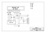
For example below is a schematic for using a 20m2 with a LCD in parallel controlled from the "C" bank.
Note...... the dispay shown is a bit strange in its pinout locations to a general 1602, but if the LCD pins are connected as per the schematic for RB4, RB5, RB6, RB7, EN, RS then any 1602 display can be used.
If needed i can offer a basic LCD code example to suit the schematic.
For example should you choose to use the LCD in parallel mode like i do, then i just use the "C" bank for the LCD, leaving all the "B" bank pins for other tasks, including the I2C pins free.
Basically splitting the chip in half with one side for the LCD and the other side for all other tasks.
This also makes the code easier should you use commands like "Let PinsC = xxxxxx" as it dont effect the PinsB. whist used for other functions.
If you are somewhat new to picaxe and programming then the 20m2 would be the far better option due to the ease of driving the LCD from one bank without the concern of not using the I2C pins and splitting the LCD across both bank "B" and bank "C" pins as required for the 18m2.
All is do able but one is far easier to code than the other.
Although should you use a serial or I2C display then none of the above views matter. (personally i would use a 20m2 and drive the display in parallel direct from the chip, then you can use any $2.00, 1602 display you like)
For example below is a schematic for using a 20m2 with a LCD in parallel controlled from the "C" bank.
Note...... the dispay shown is a bit strange in its pinout locations to a general 1602, but if the LCD pins are connected as per the schematic for RB4, RB5, RB6, RB7, EN, RS then any 1602 display can be used.
If needed i can offer a basic LCD code example to suit the schematic.
Last edited:
What is the project? That determines which PICAXE you should use.I am working on a project that requires a 16x2 LCD screen and a RTC module (I2C). If you had a choice between the 20M2 or the 18M2+...which one would you choose. The cost of the chips are exactly the same.
The PICAXE-20M2 can be upgraded easily to a PICAXE-20X2. The PICAXE-20M2 has two extra pins but these are just for the purpose of having dedicated programming pins so if you are using all the pins and you have components that would be sensitive to the serial programming signals then using a PICAXE-20M2 would have an advantage, but if this is not a problem and you don't think you'll ever need to use a PICAXE-20X2 then the extra pins might just be wasting space without having any particularly useful purpose. If space is at a premium, then the PICAXE-18M2 is the better choice.
Don't forget the PICAXE-18M2 allows you to use both the serial programming pins as general purpose I/O (input using disconnect command).
If you have a lot of space to spare then the PICAXE-20M2 is the better choice because of the ability to replace it with a PICAXE-20X2 and because the PICAXE-20M2 is 10p cheaper than the PICAXE-18M2 from the PICAXE Store.
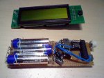
It does not require much effort to use an 8-bit or 4-bit LCD/OLED at the same time on either PICAXE (see picture above - 8 pin IC is DS1307 and 8 bit LCD is used).
westaust55
Moderator
The two extra pins on the 20M2 are not dedicated purely for programming. Using the SERTXD and SERRXD commands they are also available for serial comms to terminal software on a PC or other device using a compatible baud rate (4800, 9699, etc).
Two exta pins means the DIP chip is 0.1 inch / 2.54 mm longer - hardly a massive additional space requirement for most projects.
Two exta pins means the DIP chip is 0.1 inch / 2.54 mm longer - hardly a massive additional space requirement for most projects.
Basically nick12ab...my project is pretty straight forward. I am building a device that needs a simple 16x2 display for displaying a message and then sampling a RTC for the time and date and then display that. I was wanting to use the LCD in 8 bit mode so I did not have to worry about programming space with doing the display in 4 bit mode. I know the 18m2+ has more space now but you never know what other crazy things I would want to try. LOL I could actually use the 14m for the project because I also am playing around with the phanderson 1307 chip. I don't think they sell them anymore so I have figure out an alternative. I am also trying to keep the cost down because once I finish the project I might go into a small production run on them and sell them.
Dont 8 bit mode require 10 output pins to drive the LCD compared to 6 pins for 4 bit mode.I was wanting to use the LCD in 8 bit mode so I did not have to worry about programming space with doing the display in 4 bit mode.
Also i dont see where the programming space is a problem with 4 bit mode as its just a few lines of code in a sub routine that is used over and over.
The DS1307 is made by Dallas and are avalible everywhere, try ebay as there is dozens of them about.
What's that? LCD #107 chip?LOL I could actually use the 14m for the project because I also am playing around with the phanderson 1307 chip
I'd recommend that even less than a Rev-Ed serial LCD - the LCD #107 doesn't even use HD44780-compatible command codes! They just made up their own command system and it uses the question mark. Maybe he wants to make it more confusing to break free from serial LCDs and make the switch to parallel LCDs.
Plus the baud rates are fixed (unlike the FRM010) and you have to pick one when you buy it.
I've used Dr. Anderson's 107 serial LCD interface chip before in my PICAXE projects. They were inexpensive, quickly available here in the USA, (where the OP is,) and have worked fine. I don't regret purchasing them. What they lack is ready support within the PICAXE Forum since Dr. Anderson passed away, because, as mentioned, they do use a somewhat different command structure. For new users in particular, the Forum support is very valuable.