NEC format bit-banged IR output using Macros and Include files.

PhilHornby

Senior Member
I've recently embarked on a project to implement a remote thermostat for a Dimplex Opti-myst Electric Stove, since the built-in one is hopeless.

As user pleitch discovered, when trying to do something similar with a Dimplex Air-conditioner, control via the IR remote is the only way to go - control via the mains input just toggles between 'OFF' and 'Standby'.

Here is my code to implement the three buttons on the Dimplex RC02-010 Remote Control, which uses the NEC protocol. I've used the #Macro and #Include functionality of the V6.x.x.x Picaxe Editor to try and improve readability.

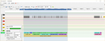
I used InglewoodPete's Background Infrared Receiver to verify the output.


This is a demo program - that just sends the 'Centre' button repeatedly.

Code:
#picaxe 08M2
;+
; NEC.BAS - Demonstrate sending NEC format IR signals, using Macro and include file
;        functionality of Picaxe Editor V6.x.x.x.
;
; Author: Phil Hornby:
;
;-
Symbol Data_Pin    = C.2                            ;connect to IR LED, or driver transistor/mosfet
Symbol Debug_Pin    = C.4                            ;20uS pulse to sync oscilloscope - if req'd


#rem


This is the o/p of this program, as decoded by 'InglewoodPete's 20X2 program:-


See: http://www.picaxeforum.co.uk/showthread.php?16576-Background-Infrared-Receiver-for-32-bit-Codes


    Start >2h-TOut-
    Start >2h
    <End 00000000111111111001000001101111>
    [42][25]%00000000.11111111 %10010000.01101111
    $00FF 906F


    which is identical to that produced by a physical Remote Control
    (Dimplex model: RC02-010, "Centre" ON/OFF Button)


    Start >2h-TOut-
    Start >2h
    <End 00000000111111111001000001101111>
    [42][25]%00000000.11111111 %10010000.01101111
    $00FF 906F


Dimplex Opti-myst (RC02-010) codes:-


LEFT (Flame)    => 0000 0000 | 1111 1111 | 0101 0000 | 1010 | 1111    (10)
CENTRE (ON/OFF)    => 0000 0000 | 1111 1111 | 1001 0000 | 0110 | 1111    (9)
RIGHT (HEAT)    => 0000 0000 | 1111 1111 | 1101 0000 | 0010 | 1111    (11)


(usually followed by one or more repeat codes - though the target hardware (a heater) ignores them.)


#endrem


#No_data
#No_end


#include "RemoteControl.basinc"


;
; Start execution
;
    setfreq M32                                ;warp factor 9


    ;dirs = %00010100                            ;Pin direction statements not needed - implied from usage


;    Loop forever, sending same code.


do
    pulsout Debug_Pin,15                        ;optional pulse to sync oscilloscope.
                                        ;15 * 1.25 = 18.75uS + 2uS overhead = 20 uS
                                       
;    SendLeftButton                            ;Send code for Left Button ('Flame')
    SendCentreButton                            ;Send code for Centre Button (ON/OFF)
;    SendRightButton                            ;Send Code for Right Button ('Heater Power')
loop

and here is where the actual work is done:-

Code:
;+
; RemoteControl.basinc - macro definitions
;
;    All timings assume 32MHz operation.


;
; Macros used in generating an NEC IR signal; these are common to all Remotes. They generate the component
; parts of the NEC protocol.
;   
    #macro StartCarrier                        ;Turn on the PWM function
        ;
        ; The carrier is generated using the inbuilt PWM function.
        ;
        pwmout Data_Pin, 210, 278                ;Start PWM output @ 38000Hz at 33% @ 32MHz (from wizard)
    #endm


    #macro SendAGC
        ;
        ; Sends 9mS worth of pulses of 8uS +16uS gap. Then pause 4.5mS.
        ; (Apparently, was used to set AGC originally.)
        ;
        StartCarrier                        ;start 38KHz carrier o/p
        pauseus 7100                        ;wait 8.875mS (7100 /8 = 887.5 * 10 = 8.875mS)
        pwmout Data_Pin,off                    ;then shut it off - it will have been active for 9mS in total.
       
        pauseus 3400                        ;Pause further 4.25mS (3400 /8 = 425 * 10 = 4.25mS)
                                    ;to bring total gap to 4.5mS (including delay in starting first 'bit' o/p,
                                    ;which follows this preamble)
    #endm


    #macro Send38KHzBurst
        ;
        ; Sends 21 pulses of 8uS +16uS gap.
        ;
        StartCarrier                        ;start 38KHz carrier o/p
        pauseus 325                        ;wait 406uS (325 /8 = 40.625 * 10 = 406uS)
        pwmout Data_Pin,off                    ;then shut it off - it will have been active for 560uS in total.
    #endm


    #macro SendZero
        ;
        ; "0" bit
        ;
        Send38KHzBurst                        ;250~270uS overhead, starting & stopping pulse train
        pauseus 226                        ;226/8 = 28.25 * 10 (283) makes total gap = 560uS
    #endm
   
    #macro SendOne
        ;
        ; "1" bit
        ;
        Send38KHzBurst                        ;250~270uS overhead, starting & stopping pulse train
        pauseus 1148                        ;1148/8 = 143.5 * 10 (1435) takes gap to 1.69mS
    #endm
   
    #macro SendEndPacket
        ;
        ; Mark the end with an extra bit and a long gap.
        ;
        Send38KHzBurst                        ;21 pulses of 38KHz carrier
        Pause 880                        ;then gap of 110mS (* 8 for 32MHz operation)
    #endm


;     Now, the Device-specific macros...
   
;
;    Macro to define the target device of a particular Remote Control.
;
    #macro SendAddress
        SendAGC                            ;marks start of packet
        ;
        ; Address Byte, LSB first "00000000" (This is Dimplex's choice...for reasons known only to them!)
        ;
        SendZero
        SendZero
        SendZero
        SendZero
        SendZero   
        SendZero
        SendZero
        SendZero
        ;
        ; Inverse of Address byte "11111111"
        ;
        SendOne
        SendOne
        SendOne
        SendOne
        SendOne
        SendOne
        SendOne
        SendOne
    #endm
;
;    Macro(s) to define each button on the Remote Control.
;


    #macro SendLeftButton
        ;
        ; Send Dimplex Opti-myst Remote Control "Left Button" ('Flame' = code 10)
        ;
        SendAddress
        ;
        ; Command byte, LSB first "01010000" (10)
        ;
        SendZero
        SendOne
        SendZero
        SendOne
        SendZero
        SendZero
        SendZero
        SendZero
        ;
        ; Inverse of Command byte "10101111"
        ;
        SendOne
        SendZero
        SendOne
        SendZero
        SendOne
        SendOne
        SendOne
        SendOne
        ;
        ; End of packet marker (33rd 'bit' and 110mS gap)
        ;
        SendEndPacket                        ;terminate the data
    #endm
   
    #macro SendCentreButton
        ;
        ; Send Dimplex Opti-myst Remote Control "Centre Button" (ON/OFF = code 9)
        ;
        SendAddress
        ;
        ; Command byte, LSB first "10010000" (09)
        ;
        SendOne
        SendZero
        SendZero
        SendOne
        SendZero
        SendZero
        SendZero
        SendZero
        ;
        ; Inverse of Command byte "01101111"
        ;
        SendZero
        SendOne
        SendOne
        SendZero
        SendOne
        SendOne
        SendOne
        SendOne
        ;
        ; End of packet marker (33rd 'bit' and 110mS gap)
        ;
        SendEndPacket                        ;terminate the data
    #endm


    #macro SendRightButton
        ;
        ; Send Dimplex Opti-myst Remote Control "Right Button" ('Heater Power' = code 11)
        ;
        SendAddress
        ;
        ; Command byte, LSB first "11010000" (11)
        ;
        SendOne
        SendOne
        SendZero
        SendOne
        SendZero
        SendZero
        SendZero
        SendZero
        ;
        ; Inverse of Command byte "00101111"
        ;
        SendZero
        SendZero
        SendOne
        SendZero
        SendOne
        SendOne
        SendOne
        SendOne
        ;
        ; End of packet marker (33rd 'bit' and 110mS gap)
        ;
        SendEndPacket                        ;terminate the data
    #endm

Attached files - RemoteControl.basinc had to be renamed to RemoteControl.bas to keep the Uploader happy...
 

Attachments

Last edited:
Thanks for putting the time and work into making this happen. I have often thought about developing an NEC code sender but got to do it.
 
Hi,

Here is an M2 program to encode any four bytes into the NEC IR transmitter format. Non-intuitively, as I've discovered before, it can be more difficult to write satisfactory code to transmit a protocol than to receive it. One reason is that the program must accurately reproduce all the protocol parameters, whilst receiving code may need only to "recognise" or synchronise to a few basic features of the coding. Also, the transmitting code here is used to modulate the carrier, whilst the receiving code is assumed to be supplied with demodulated data from the IR receiver.

Here, I've used the IR-NEC Protocol Decoder incorporated within the "PulseView" (Siglok) application, to validate the data timing. This appears to have quite critical requirements (for example it failed to "see" the "0" bits in the code from post #1), but of course doesn't indicate what it considers to be "wrong" with the data. Certainly, the timing of the (modulated) pulses and spaces is not completely consistent, which appears to be caused by the use of PWMOUT commands: Surprisingly, there are no "partial" IR pulses (which might be expected of an asynchronous modulator), perhaps because the Microchip data sheet indicates at least a capability of operating only with complete PWM cycles. However, I'm not clear if the observed inconsistency is caused by the PICaxe firmware or the base "silicon" hardware. Note that the PWMDUTY instruction is completely unusable because it takes at least 1ms to execute, even at a Setfreq M32.

The modulation can be removed (or inverted) by choosing appropriate values for DUTY and IDLE, but the uneven timing still occurs. However, it disappears if the PWMOUT commands are replaced by HIGH and LOW instructions. Another aspect of the data timing is that the PICaxe 08M2 chip executes the code significantly faster than a 20M2, so delay constants are supplied for both chips. The 14M2 timing is probably the same as the 20M2 and the 18M2 perhaps somewhere nearer to the 08M2 (because it does not need its internal ports remapped). X2s are probably even slower, but of course the clock the frequency can (and probably needs to) be increased to 64 MHz.

The structure of the program is quite critical, particularly because of the (short) timing of the NEC "0" databit, and some limitations of PICaxe Basic. The overhead on the PAUSEUS instruction (which is required twice, for the pulse and for the gap) is almost 100us at 32 MHz and the M2 has no direct "Shift" operations, nor the concept of a "Carry" flag. The NEC protocol transmits LSB first which normally would use Right-shifting, that needs the use of division. Also, copying a carry from the LSB end and adding it to the MSB end (of another word) is rather inefficient. Converesly, Left-shifting needs only multiplication by two, or even more efficiently by adding the word value and a carry value to itself, all in a single instruction line.

Therefore, the program uses only Left-Shifts and reverses the bit-order within the bytes before transmission. This could be performed in the initial data preparation, but a simple algorithm fits in neatly during the "AGC" pulse (or even during the "header" gap). An efficient "Mirror" reversing algorithm (also available as REV in X2s) is a topic that could fill a thread in itself, but the required bit-swapping is sufficiently "untidy" that the simple BITn re-assignments are the most efficient (or a 256 Byte Table-Lookup is easily the fastest).

For testing and demonstration, the code alternates Normal and Repeat packets, whilst in practice it appears that the Repeats should continue until a button is released. Many of the instruction line comments include an estimation of their execution period in PIC Instructions, which correspond to 125ns at a Setfreq of 32 MHz. Hopefully, I'll post a corresponding decoder routine in a suitable location on the forum, in due course.

Code:
; NEC InfraRed Encoder.  AllyCat January 2021
#picaxe 08M2   	 	; Faster than other M2s
;  #picaxe 20M2		; Slower than some M2s
#no_data

calibfreq 0			; 16 increases frequency by 1.6% (228 increases period by 3%)
setfreq m32
symbol tempb = b1						; Bit-addressable
symbol tempw = w1						; Bit-addressable
symbol wx = w2							; NEC Address (& complement)
symbol wy = w3							; NEC Command (& complement)
symbol PERIOD 	= 210					; For 38.5 kHz @ 32MHz
symbol DUTY 	= 900	;280					; Carrier DutyCycle (844 = 100%)
symbol IDLE 	= 0 							; Idle Low (900 for High)
symbol DATABITS = 64 + 32					; 64 gives Active low flag (33 counts to bit14 = 0)
; Timing Constants
	#IFDEF 08M2
symbol WidAGC 	= 4420				; Pauseus units = 0.125us
symbol WidHDR 	= 3200				; 4.5 ms standard Header Gap
symbol WidPUL0 = 88 					; For 0 Data pulse
symbol WidPUL1 = 200					; For 1 Data pulse
symbol WidGAP0 = 110					; For 0 Data Gap
symbol WidGAP1 = 820					; For 1 Data Gap
symbol DelREDO = 327 					; Pause (125us units) to next transmission
symbol WidAGCT = 7000				; Repeat AGC pulse width (no mirror code needed)
symbol WidHDR2 = 1600				; 2.25 ms Repeat Header Gap
symbol WidPUL 	= 360				; Repeat code pulse width
symbol DelREPT = 780					; Pause after Repeat burst
	#ENDIF
	#IFDEF 20m2						; Probably also for 14M2
symbol WidAGC 	= 4000 				; Pauseus units = 0.125us
symbol WidHDR 	= 3000 				; 4.5 ms standard Header Gap
symbol WidPUL0 =   35					; For 0 Data pulse
symbol WidPUL1 =  160 				; For 1 Data pulse
symbol WidGAP0 =   35 				; For 0 Data Gap
symbol WidGAP1 =  700 				; For 1 Data Gap
symbol DelREDO =  313					; Pause (125us units) to next transmission
symbol WidAGCT = 7130				; Repeat AGC pulse width (no mirror code needed)
symbol WidHDR2 = 1620				; 2.25 ms Repeat Header Gap
symbol WidPUL 	=  300				; Repeat code pulse width
symbol DelREPT =  772					; Pause after Repeat burst
	#ENDIF
symbol PWMop 	= c.2				; Transmit Output pin

main:
do
	b4 = 25							; Address
	b5 = b4 xor 255					; Extended (complement) Address
	b6 = 29							; Command
	b7 = b6 xor 255					; Command Complement 
	call NEC_TX
	pause DelREDO					; Frame repeat = 110 ms
	call NEC_RPT
	pause DelREPT	
loop

NEC_TX:
SendAGC:								; Framing pulse of continuous carrier (typically 9ms)
	pwmout PWMop,PERIOD,DUTY			; For 9 ms burst of 38kHz
Mirror:									; Reverse the bit sequence to allow Left-Shifts
	bptr = 4								; Address/Command Register address (bytes 4 to 7)
do										; \/PIC Instruction Cycles
	b3 = @bptr							; 500  ; Must be bit-addressable
	bit16 = bit31 : bit17 = bit30 ; 940
	bit18 = bit29 : bit19 = bit28 ; 940
	bit20 = bit27 : bit21 = bit26 ; 940
	bit22 = bit25 : bit23 = bit24	; 940
	@bptrinc = b2						; 500 + 4760 * 4 = 19040
loop until bptr = 8					; 4400
	b1 = b4 : b4 = b7 : b7 = b1	; 1500		; Swap bytes
	b1 = b5 : b5 = b6 : b6 = b1	; Total swap = 3.3ms @ 32MHz
	pauseus WidAGC						; 700 + 10N ICs
	pwmout PWMop,PERIOD,IDLE			; 800		
Header2:									; Typically 4.5ms
	pauseus WidHDR						; 700 + 10N
	b1 = DATABITS						; 500		; Number of bit pulses 
	w1 = wx								; 500		; To allow flag-testing
Sendbit:									; Nominal bit-pulses = 562ms
	on bit14 goto bitsdone					; 500 	; Fall through until bit14 = 0 (900 ICs)
Pulse:									; 562us = 4500 ICs @ 32MHz
	dec b1								; 600
	pwmout PWMop,PERIOD,DUTY		; 800 		; Start pulse
	if wy > 32767 then longgap			; 800		; Jump for long bit period
	wy = wy + wy + bit31				; 900		; Shift left and get carry
	w1 = w1 + w1						; 600
	pauseus WidPUL0					; 700 + 10N
Gap:										; 562us gap
	pwmout PWMop,PERIOD,IDLE		; 800		; End of pulse
	pauseus WidGAP0					; 700 + 10N
 	goto sendbit						; 800	
Longgap:									; ~1.7ms
	pauseus WidPUL1					; 700 + 10N
Gap1:
	pwmout PWMop,PERIOD,IDLE	 	; 800		; End of pulse
	wy = wy + wy + bit31 				; 900 	 	; Shift left and get carry
	w1 = w1 + w1 					; 600		; Shift Low word Left
	pauseus 	WidGAP1				; 700 + 10N
	goto sendbit						; 800
Bitsdone:								; (Total ~150 bytes)
 return

NEC_RPT:
Repeatcode:
	pwmout PWMop,PERIOD,DUTY		; 800		; Start pulse
	pauseus WidAGCT					; 900 * 8 - 700 = 7130
	pwmout PWMop,PERIOD,IDLE		; 800		; End of pulse
	pauseus WidHDR2					; 225 * 8
	pwmout PWMop,PERIOD,DUTY		; 800 	 	; Start pulse
	pauseus WidPUL					; 562 * 8
	pwmout PWMop,PERIOD,IDLE		; 800		; End of pulse
return									; (Total ~45 bytes)

NEC_IR_08M2..png

Cheers, Alan.
 
Hi,
I'll post a corresponding decoder routine in a suitable location on the forum, in due course.
I think this thread is probably the most suitable location for the Receiving Code, but first an "update". ;)

It would have been possible to "reverse" my above transmitter code, both figuratively and literally (e.g. using Right-Shifts in place of Left-Shifts) but my "preference" is for code that can run at 16 MHz. Not an easy challenge with already quite efficient code at 32 MHz, but I did find a few "tricks" to draft a viable 16 MHz Program. However, it was far from elegant and not comparable with Pete's beautifully documented "background" routine, linked earlier in this thread, so I put mine "on the back burner".

Then, an interesting enquiry in the Active Forum raised issues with PICaxe's Sony/IRIN command, which is not necessarily "better" or "worse" than the NEC protocol ("horses for courses"), but it is "different". It raised a few more ideas for "tricks" and I subsequently posted a 12-bit IR Decoder Code Snippet for the Sony/IRIN protocol in the Finished Projects section, which can work reliably at 16 MHz. Some of the principles described there have now been incorporated into the NEC code, so won't necessarily be described again here.

To devise the above, I had needed a "test transmitter", so I programmed an 08M2 with a single IROUT instruction within a few nested loops. This gave the opportunity to include a slightly modified version of my NEC code from above, but without the "Repeat" packets. The PICaxe/Sony IROUT signal is modulated (at 42 kHz) and had needed a simple R-C Low-Pass filter to retrieve the Raw Data for experimental decoding, so I adapted the NEC code to give Modulated and Raw (Baseband) outputs on the two spare pins. Easily done by just adding a LOW or HIGH pin command adjacent to each PWMOUT ...... instruction, and reducing the associated calibration time delays by about 40 units (i.e. 50 us at 32 MHz). Not really a Finished Project (at least by my standards), but it does sequentially transmit all "possible" codes (and the Raw Duty Cycle output does appear more consistent), so I'm attaching the adapted Program here for reference.

Thus, the "Sony/IROUT" project gave some more food for thought on decoding the NEC protocol (at 16 MHz) and I do now have a functional decoder program for the NEC protocol, that I plan to post here soon. But first, perhaps it's worth giving a brief comparison of the two protocols for anyone considering an "end-to-end" system design: For PICaxe users, the Sony is the obvious choice because of the embedded IRIN and IROUT commands, even in the 08M2. Up to "128 buttons" should be sufficient for most Remote Control applications (and my new code snippet offers all 12 bits, or 4096 "codes" from the IROUT instruction, if required). It's also quite "fast", transmitting each packet in 20 ms or less, compared with about 70 ms for the NEC protocol, but the Sony has no specific Error or Validity checking.

IMHO, the NEC protocol seems quite a "strange" choice, particularly for "simple" Remote Controls such as a heater; The 32 data bits and 70 ms transmission time appear excessive, but maybe allow for a vast range of different dedicated "Manufacturer Code" allocations. The recommended repetition of (Inverted) bytes reduces the capacity to 16 bits with some "protection", but again seems a strange choice, particularly in association with their "Repeat Code" concept. The inverted/duplicated bytes do give a constant message duration (always an equal number of 0 and 1 bits) but almost doubles the transmission time and gives only intrinsic Error Detection, not any direct Error Correction capability.

Normally, a simple Correction strategy would use a "majority decision" (i.e. from 3 consecutive, identical packets) and/or a two-dimensional checksum array. Therefore, combined with the "Repeat" packet header (i.e. no actual data bits transmitted; they are assumed to be unchanged), the consequence of one, or a few, "bad" bits in the first message can potentially produce an "Unrecoverable Error" (unknown value) regardless of how long the "transmitter button" is pressed. But in practice, some error correction capability may be possible if the designer has read up his theory on Hamming Distance. ;)

Finally, just a few more "cons": The overall transmitting duty cycle is around a greedy 65%, (i.e 70 ms in 110 ms), which is probably why the "Repeat" option was devised. Also, the LS Bit-first coding implies Right-Shifting, which cannot be programmed as efficiently as Left-shifting in M2 PICaxes, particuarly if the bits are not directly-addressable. The same does apply to the Sony and even RS232 formats, but 32 is the full availability of PICaxe individual bits (i.e. in b0 - b3, or w0 and w1); I wouldn't want to allocate all those bits to a single Code Snippet or Subroutine, and also the coding introduces a 33rd pulse (to terminate the 32nd bit), which might initiate another bit-period and cause an overflow. Combined with PICaxe Basic's lack of a "Carry" flag, this implies that a 3rd Word may need to be added to the Shift Register, whilst the 12-bit Sony protocol fits easily within one.

I'd intended to attach the test transmitter program as a file, but as I'm still (just) within the 10000 character limit, it might as well be in-line. ;)
Code:
; Test Transmitter for 12-bits Sony IR Protocol (IROUT) and NEC 32-bits 
; AllyCat March 2021
; Use 2n2 // 10k {with pullup diode} filter on C.1 to demodulate
#picaxe 08m2
#no_data
sertxd("IRout test on c.1 (Sony); c.2 (NEC-mod) & c.4 (NEC-raw)",cr,lf)
symbol CALVDD = 52429    	; 1024*1.024*1000/20  (ADC steps * Ref V / Resolution in mV)
symbol SIRCout = c.1		; Modulated
symbol NECmod = c.2		; PWM output
symbol NECout = c.4		; Unmodulated
pause 1000
do
for b11 = 1 to 255
	calibadc10 w1        				; Measure FVR (nominal 1.024 v) relative to Vdd (1024 steps)
	w2 = w1 / 2 + CALVDD			; Effectively round up CALVDD by half a (result) bit
	w2 = w2 / w1        				; Take the reciprocal to calculate (half) Vdd (tens of mV)
	calibadc10 w1        				; Read the value again because noise may be present :)
	w1 = CALVDD / w1 + w2		; Calculate Vdd/2 again and add in the first value
	sertxd(#b0," Vdd= ",#w1,"0 mV",cr,lf)
	for b10 = 0 to 255
		sertxd(#b11,":",#b10," ")		; Report the supply voltage
		irout SIRCout,b11,b10		; Send the Sony data packet (4 MHz clock)
		setfreq m32
		b4 = b11					; Address
		b5 = b4 xor 255			; Extended (complement) Address
		b6 = b10					; Command
		b7 = b6 xor 255			; Command Complement 
		call NEC_TX
		setfreq m4
	next
next
loop

symbol tempb = b1				; Bit-addressable
symbol tempw = w1				; Bit-addressable
symbol wx = w2					; NEC Address (& complement)
symbol wy = w3					; NEC Command (& complement)
symbol PERIOD 	= 210			; For 38.5 kHz @ 32MHz
symbol DUTY 	= 280				; Carrier DutyCycle (844 = 100%)
symbol IDLE 	= 0 					; Idle Low (900 for High)
symbol DATABITS = 64 + 32			; 64 gives Active low flag (33 counts to bit14 = 0)
; Timing Constants
	#IFDEF 08M2
symbol WidAGC 	= 4310	; 4420	; Pauseus units = 0.125us
symbol WidHDR 	= 3300	; 3200	; 4.5 ms standard Header Gap
symbol WidPUL0 = 32		;   48	; For 0 Data pulse
symbol WidPUL1 = 144		;  160	; For 1 Data pulse
symbol WidGAP0 = 100		;  70		; For 0 Data Gap
symbol WidGAP1 = 820		;  780	; For 1 Data Gap
symbol DelREDO = 287		;  327 	; Pause (125us units) to next transmission
	#ENDIF
symbol PWMop 	= c.2			; Transmit Output pin

NEC_TX:
SendAGC:							; Framing pulse of continuous carrier (typically 9ms)
	high NECout
	pwmout PWMop,PERIOD,DUTY		; For 9 ms burst of 38kHz
Mirror:									; Reverse the bit sequence to allow Left-Shifts
	bptr = 4								; Address/Command Register address (bytes 4 to 7)
do											; \/PIC Instruction Cycles
	b3 = @bptr							; 500  ; Must be bit-addressable
	bit16 = bit31 : bit17 = bit30 ; 940
	bit18 = bit29 : bit19 = bit28 ; 940
	bit20 = bit27 : bit21 = bit26 ; 940
	bit22 = bit25 : bit23 = bit24	; 940
	@bptrinc = b2						; 500 + 4760 * 4 = 19040
loop until bptr = 8					; 4400
	b1 = b4 : b4 = b7 : b7 = b1	; 1500		; Swap bytes
	b1 = b5 : b5 = b6 : b6 = b1	; Total swap = 3.3ms @ 32MHz
	pauseus WidAGC						; 700 + 10N ICs
	low NECout
	pwmout PWMop,PERIOD,IDLE			; 800		
Header2:									; Typically 4.5ms
	pauseus WidHDR						; 700 + 10N
	b1 = DATABITS						; 500		; Number of bit pulses 
	w1 = wx								; 500		; To allow flag-testing
Sendbit:									; Nominal bit-pulses = 562ms
	on bit14 goto bitsdone			; 500 	; Fall through until bit14 = 0 (900 ICs)
Pulse:									; 562us = 4500 ICs @ 32MHz
	dec b1								; 600
	High NECout
	pwmout PWMop,PERIOD,DUTY		; 800 		; Start pulse
	if wy > 32767 then longgap		; 800		; Jump for long bit period
	wy = wy + wy + bit31				; 900		; Shift left and get carry
	w1 = w1 + w1						; 600
	pauseus WidPUL0					; 700 + 10N
Gap:										; 562us gap
	low NECout
	pwmout PWMop,PERIOD,IDLE	; 800		; End of pulse
	pauseus WidGAP0				; 700 + 10N
 	goto sendbit					; 800	
Longgap:							; ~1.7ms
	pauseus WidPUL1				; 700 + 10N
Gap1:
	low NECout
	pwmout PWMop,PERIOD,IDLE	; 800		; End of pulse
	wy = wy + wy + bit31 			; 900 	; Shift left and get carry
	w1 = w1 + w1 				; 600		; Shift Low word Left
	pauseus 	WidGAP1			; 700 + 10N
	goto sendbit					; 800
Bitsdone:			; (Total ~150 bytes)
 return

Cheers, Alan.
 
Last edited:
Hi,
Hopefully, I'll post a corresponding decoder routine in a suitable location on the forum, in due course. .....
I think this thread is probably the most suitable location for the Receiving Code,....
Nearly four years on from the above post, but when responding to a recent thread in the Active Forum, it appears that I didn't ever post my prepared NEC Receiving code. :( At the time, I believe the reason for delaying the post was that the Samsung Protocol seemed so similar to NEC, that it would be worthwhile to incorporate. However, looking back at the Program file now, and the Transmitting code in #3 above, it appears that both can be improved or updated. Since the primary topic of this thread is Transmission of the protocol, I'll start with that, hopefully followed soon by the Receiver Code. I'll try to avoid repeating too much detail already covered in this thread, so the new Encoder Program description will follow on from the content in post #3, and the Receiver / General Discussion from post #4.

Reading the Data Sheet(s) for a typical three-terminal Infra Red receiver, which will nearly always be used with any Receiver (code) gave some food for thought. In particular it specifies that for a "perfect" modulated square wave IR input signal of 600 : 600 microseconds ratio (carrier to gap), the decoded output wave may have a ratio between 400 : 800 and 800 : 400 microseconds (presumably caused by asymmetric delays of the rising and falling edges). This range might seem over-pessimistic, but there are many other "unknowns", particularly of the PICaxe Instruction Execution times, so this seems a reasonable overall design target. It should be noted that the Period of the output waveform is NOT affected, because this is measured between edges of the same polarity.

Of course this mainly affects the design of the Receiver (code), but suggests that it is not vital for the Transmitter Program to achieve a "perfect" 50 : 50 % Duty Cycle. Also, the observation in #3 that the PWM carrier pulses are always of complete-width, means that the nominal 21 - 22 carrier pulses (at 38.2 kHz) may dither by +/-1 pulse, or a +/-5% variation. Therefore, a single PAUSEUS instruction can be sufficient to "calibrate" the (Data 0) Loop Period, with the overall Duty Cycle determined by careful selection of the position and type of Instructions contained in the "Pulse" and "Gap" sections. The time released by removing one PAUSEUS from the program loop in #3, combined with some improved coding structures, has made it possible to directly use Right-Shifting of the data bits (i.e. deleting the bit-swapping "Mirror: " section of the program) and to introduce a few new features.

Personally, I prefer to post my Program Listings "In Line" (i.e. not as an attached file) so I am already nearing the forum's 10,000 character limit for each post. Therefore, here is the Full Program and I will continue with its description in my next post:

Code:
; NEC InfraRed Encoder.  AllyCat January 2025
;#picaxe 08M2          ; Faster than other M2s
#picaxe 14M2
;#picaxe 20M2          ; Slower than some M2s
#no_data
#DEFINE FLEX          ; Address, Command Data & AGC/Header formats are Flexible via byte b1 flags
calibfreq 0           ; 16 increases clock frequency by ~1.6%, 224 (-32) decreases frequency by ~3%
setfreq m32           ; Instruction Cycle = 125 ns, PAUSEUS units 1.25 us, PAUSE units 0.125 ms
symbol tempb = b1               ; Bit-addressable / mode / bit counter
symbol tempw = w1               ; Bit-addressable / NEC Address and/or Command bytes
symbol wx = w2                  ; Command Word/byte (& complement)
symbol wy = w3                  ; (Optional) Carry Flag (Delay / multiplier) Word (to top of SR)
symbol NoRpt = bit9             ; Always send full Data Packets (no Repeat packets)
symbol PERIOD   = 208           ; For 38.2 kHz PWM @ 32MHz (PWMDIV4 may execute slightly faster)
symbol DUTY     = 276           ; Carrier Duty Cycle for 33% (837 = 100%)
symbol IDLE     = 0             ; Idle Low (840 for Idle High)    
symbol PWMop    = b.2           ; Transmit Output pin
symbol DelREDO  = 313           ; Pause (125us units) to next transmission
symbol DelREPT  = 772           ; Pause after Repeat burst
symbol TRIMGAP  = 56            ; Trim Data 0 Modulation Gap and cycle period
symbol ONEGAP   = 640           ; Additional Gap delay for Long (Data 1) bit
symbol WidPUL1  = 200           ; Width of first pulse after Header/Framing Gap
symbol WidAGC   = 34            ; Half NEC AGC pulse (= 4.5 ms = Samsung), 125us units
symbol WidHDR   = 1600          ; Half Header gap (= 2.25 ms = Repeat), 1.25 us units
symbol STEPC    = 4             ; Loop counter decrement, to permit perpetuity of bit8, bit9 Flags

main:                           ; Might be located later in the Program
do
    b1 = $8C                    ; Loop count and various configuration flags
    b2 = $12                    ; True 8-bit Address
    b3 = $ED                    ; Complement Address or 16-bit High Address (expA clear)
    b4 = $55                    ; True 8-bit Command
    b5 = NOT b4                 ; Complement Command or 16-bit High Command (expC clear)
    w3 = 0                      ; Reserved for (optional) carry bit    (*$8000) 
    call NEC_TX
    pause DelREDO               ; Frame repeat = 110 ms
    call NEC_TX                 ; Assuming Automatic Repeat
    pause DelREPT
loop
    
    goto main                   ; Locating time-critical subroutine(s) at the start/top __
NEC_TX:                         ; __ may help stabilise execution times
#IFDEF FLEX                     ; For extended functions via b1 flags
symbol AGC_2 = bit8             ; Flag to use Shorter (4.5ms) AGC pulse (Samsung)
symbol expA  = bit10            ; Flag to add complement for 8 bit Address (Auto-cleared after use) 
symbol expC  = bit11            ; Flag to add complement for 8 bit Command (cleared after use)

    if expA = 1 then            ; Address complement flag
        if expC = 1 then        ; Both bits set
            b4 = b3             ; Copy High byte (8-bit Command) to Low Command byte
        endif
        b3 = NOT b2             ; Write complement to (High) Address byte
    endif
    if expC = 1 then            ; Command complement flag
        b5 = NOT b4             ; Write complement to (High) Command byte
    endif
SendAGC:
    pwmout PWMop,PERIOD,DUTY    ; For 9 ms burst of 38kHz
    pause WidAGC                ; 700 + 10N ICs        Half period of NEC AGC pulse (=Samsung)
    if AGC_2 = 1 then EndAGC    ; Jump for 4.5 ms AGC Pulse (Samsung)
    pause WidAGC                ; Extend pulse for standard NEC protocol
EndAGC:
#ELSE                           ; Fixed length of NEC AGC pulse
    pwmout PWMop,PERIOD,DUTY    ; For 9 ms burst of 38kHz
    pause WidAGC : pause WidAGC ; Or use a single symbol = WidADC * 2 + 70
#ENDIF  ; FLEX
                                ;  \/ = Typical Base PIC Instruction Cycles (125 ns at 32 MHz)
    pwmout PWMop,PERIOD,IDLE    ;  800    ; Start Framing Gap    
    pauseus WidHDR              ;  700 + 10N  Header Gap
    if b1 < 4 then Firstpul     ; 1200   ; Jump for Half-width Gap of Repeat Packet     
    b1 = b1 AND $F3             ;  800   ; Clear the Data Format flags for bit counter use
    pauseus WidHDR              ;  700 + 10N  Non-Repeat-Packet Gap delay 
Firstpul:
    pwmout PWMop,PERIOD,DUTY    ; 1000   ; Start 1st Data pulse
    pauseus WidPUL1             ; 2700   ; Nominal bit-pulses = 562ms = 4500 ICs
    goto Pulsend                ;  800   ; Jump into the bit loop (32.5 bits) bypassing first shift
Sendbit:                        ;(2700)  ; Delay after jump-back = 2000 - 2200 ICs
;        on bit16 goto Gapend   ; 1100   ; Option to Skip over an in-line code segment
    if bit16 = 1 then Longgap   ;  800   ; This Fall-through to Gapend is faster than a Skip
;Longgap                             ;  400   ; Locating this code in-line adds ~300 ICs to 0 loop
Gapend:                         ;        = ~ 3500 ICs to here
    pauseus TRIMGAP             ; 1000   = Trim Data-0 Gap, End of GAP here = 4500 ICs
    pwmout PWMop,PERIOD,DUTY    ; 1000   ; End the Data Gap (3500 ICs to next)
    w1 = w1 ** 32768            ; 1000   ; Shift w1 right during pulse ( /2 slower, ** Wn faster)
    bit31 = w2                  ;  600   ; Carry w2 bit 0 to w1 top bit 
    w2 = w2 ** 32768 + w3       ; 1300   ; Shift w2 right, adding top bit  (+w3 optional)
;    w2 = w2 + w3                    ;  600   ; Slower than above but can use bytes or separated from SR
    b1 = b1 - STEPC             ;  600   ; Loop counter       PULSE  = 4500 ICs to here
Pulsend:
    pwmout PWMop,PERIOD,IDLE    ; 1000   ; End the pulse
    w3 = 0                      ;  500   ; (Optional) Clear Carry Word
    if b1 > 3 then Sendbit      ; 1200   ; Loop back until bit count is complete
    if NoRpt = 1 then
        b1 = b1 + 128                    ; (Optional) To cancel Auto-Repeat packets
    endif
return                                   ; Returns 0-3 for automatic Repeat packet
Longgap:                        ;  400   ; Code to extend "1" Data Bit
    w3 = 32768                  ;  700   ; Store the LSb to add to MSb ($8000) after shifting
    pauseus ONEGAP              ; 6400   ; = 9000 - 2600
    goto Gapend                 ;  800   ; Return to the main loop

Cheers, Alan.
 
Hi,
The time released by removing one PAUSEUS from the program loop in #3, combined with some improved coding structures, has made it possible to directly use Right-Shifting of the data bits ... and to introduce a few new features.:

This required a detailed knowledge of the execution times of all the relevant PICaxe instructions, which are not formally documented mainly because they are "variable", for various reasons explained elsewhere. However, many years ago I devised a Program which can measure the typical execution times of nearly all PICaxe (M2) instructions, needing only a "real" operating PICaxe chip (not the simulator) and the Program Editor (PE5/PE6). I've used it extensively to measure the Execution Times of all the instructions above, in terms of the (typical) number of "Base PIC Instruction Cycles", where each takes exactly 1 microsecond with a 4 MHz clock, or 125 ns at 32 MHz. Generally, when using higher clock frequencies (e.g. x 8 for the 32 MHz here), I "normalise" the timing calculations to the 1 us units, by multiplying up the "available time". Thus the target for the critical "Data 0" encoding/loop time here is 1125 (us) * 8 = 9,000 ICs, with a further 9,000 ICs added (to the carrier Gap) when a "Data 1" is to be transmitted.

9,000 Instruction Cycles might seem a large number, but even the simplest PICaxe instructions take 300 - 600 ICs and the three most important, i.e. "Branch" (e.g. IF .. THEN ... ) , "Step/Shift Word Right" (divide by 2) and "Carrier On/Off" (PWMOUT ...), each average around 1,000 ICs. To achieve a 50% Data Modulation Duty Cycle, the critical, repeating "Data 0" Program Loop needs two diametrically opposite PWMOUTs separated by two groups of 3500 ICs, into which all the other instructions must be fitted. The loop requires two Branches, the first introduces a timed delay which signals that a Data 1 is being transmitted. The neatest structure would simply skip over a suitable PAUSEUS instruction in the main loop, but the "Jump" takes longer to execute than a "Fall Through". Therefore, the default here is to "GoTo" a PAUSEUS with a "GoBack" contributing to the overall "1" delay. But the time-saving in the main loop is only about the same as the shortest Padding instruction available. The second Branch is needed to Exit from the main loop when the correct number of Data Bits has been transmitted, indicated by a Loop Counter (e.g. DEC B1) which contributes around 600 ICs delay to each pass around the loop. However, this Branch can be used also to Jump "Backwards" in the Program List, to close the Loop. At 1,200 Instruction Cycles, this takes longer than the alternative Fall-Through, but less than when combined with a separate GOTO (800 + 800 = 1,600 ICs).

The "Heart" of the routine is a (software) Shift Register of 32 bits (to serialise the bits during transmission), which uses the bit-addressable W1 for its Low 16 bits, so that its end bits can be directly accessed, but the High Word (e.g. W2) must use a standard Word register. Normally, Right-Shifting (with an M2) would use a / 2 (division) operation (which is usefully faster than division by any higher number) but multiplying by "one half" by employing a ** 32768 operation is marginally faster, so used by default. Actually, multiplying by a Variable (e.g. ** S_W2), which has been pre-loaded with 32768 (or $8000) is even faster. Thus there are two opportunities to adjust the loop delay (or Duty Cycle) up or down slightly from the default value if required. The "carry" bit is copied between the two Words with a BIT16 = W2 instruction (typically 600 ICs), without the need for an AND $0001 and/or adding a * $8000 if bit-addressing were not available. But the "Shift Register" still consumes over 25% of all the loop Instruction Cycles.

A potentially useful feature is to configure the SR as a closed loop, so that the original values are restored after all the bits have been transmitted. The Low end bit is directly accessible but the top bit of the (non-bit-addressable) Upper Word can be set only by an Add or OR operation of 32768 (i.e. $8000). However, when the Low end bit is set, the "Data 1" delaying path must be followed, so there is ample time to setup a "weighted" flag. Then the only actions that are required in the critical "Data 0" loop are adding in this weighted flag (300 ICs if combined with the shifting expression) and clearing the flag (by writing zero) just before the Branch (to ensure that the flag is clear when the delay branch is not followed). This feature has been included in the default Program, but could be omitted (i.e. replaced by padding or other instructions) to give larger timing margins, or other desired facilities (e.g. HIGH and LOW pin commands to give an Unmodulated Data Output stream). [ Note: This paragraph has been heavily edited to keep within the 10,000 characters post limit. :( ]

The program has been validated mainly by using the "IR-NEC" Protocol Decoder in the Open Source Pulseview/Sigrok Logic Analyser (PC Software) in association with one of the tiny, low-cost "USB, 8-channel, 24 MHz" hardware modules, still available from around 5 £/US$ upwards. As mentioned in #3, the NEC Analyser's timing requirement is quite critical; it seems to ignore "0" bits if their period is longer than around 1.16 ms, only about 4% longer than the nominal 1.125 ms value. This seems strange when the "1" bit is 100% longer (at 2.25 ms), so a general purpose decoder would be expected to discriminate at a period of around 1.6 ms. Perhaps it intentionally rejects a bit period of 1.20 ms, which is the nominal value used by the Sony (SIRC) protocol. Also annoying with the Sigrok NEC decoder, is that IF the two Address bytes are not perfectly complementary (which is not a requirement in similar protocols such as from Samsung), then it reports an "Address Error" and doesn't decode or report the Command byte(s). The hardware still can be used for optimising the Program timing, but equally a simple 'scope, such as the PICaxe Store's PCB Scope, can be used to check the Pulse timing and the "Data Eyes" (in "Persistence" mode), etc..

The vast majority of Infra-Red Remote Controls and Receivers now use Crystal Resonators, so the frequencies and timing periods should be very accurate. However, I would still expect most receivers to be more tolerant of timing errors than the Sigrok Analyser; Certainly my PICaxe NEC Decoder will be, at least for lower frequencies (i.e. longer Pulse, Gap and Period times). Applying the Program to other (M2) chips might need some adjustments, particularly for the 08M2 which probably will require adjustment of the Delay Parameters and perhaps some "Padding" in the critical "0" timing loop. The shortest separate "NoOp" (No Operation) instruction is PAUSE 0 (300 - 400 ICs), whilst PAUSEUS 0 is around 600 ICs and then continues in 10 ICs steps from 700 upwards. There are a few other instructions such as B0 = B0 , etc., which can fill in the gap between 300 and 600 ICs.

Apart from removing the "Optional" instructions, there isn't much scope for increasing the program loop frequency, but there are a few "alternative" instructions which have been mentioned above or in the Program listing. Also, the CALIBFREQ instruction does give around +/- 3% adjustment which might be sufficient to save the day, or at least be useful to check that the timings aren't "On the Edge". Finally, it might be worthwhile to locate the encoding Subroutine an the very top of the program space (below only a GOTO init or similar), to avoid any timing changes whenever the remainder of the program is edited. But I haven't done this myself, because I would prefer to be aware if any "dangerous" variations are occurring in the timing (which I haven't encountered with the Program so far).

As already indicated, there are various derivatives of the original NEC implementation, that could be "hard-wired" (or written) into the Program Code. However, a single Conditional Compilation option (#IFDEF) named "FLEX"(ible) allows some parameters to be controlled "on the fly", rather like a Library routine. It uses the flags in register B1, in addition to W1 which contains the normal Address (and Command) bytes. Within the routine, B1 is used as a loop counter (up to 33, so 6 bits are required), but two "Persistent" flags (Bit8 and Bit9) can be used "Globally" (i.e. inside and outside of the program). Bit8 is currently used to reduce the "AGC" pulse from 9 ms (NEC) to 4.5 ms (Samsung). Some versions of the protocol permit a 16-bit Address field (i.e. no complementary/verification bits) in which case the Command Byte (or Word) is supplied in W2. Currently, Bit10 instructs the program to generate the Complementary Address in B3 (moving the Command byte to B4 (W2) if appropriate), and Bit11 generates the Complementary Command byte (to replace W2 bits 8 - 15). Complementing only the Address byte has not been seen and is not supported. It is appropriate to apply these changes only once to the received data, therefore the flags are cleared after use, so that the bits can be employed as part of the loop counter. The subroutine always generates a "Repeat" packet (2.25 ms Framing Gap with no Data bits) if the top 6 bits of B1 are all cleared. Currently, this is automatically set after the first full transmission, but can be cancelled by setting Bit9 on entry.

Finally, here is a typical Pulseview/Sigrok capture of a sample data packet from the posted Program. Of course there is much more detail to be seen when one zooms in towards the microsecond timescale.

NEC-SRflex.png

Cheers, Alan.
 
I do now have a functional decoder program for the NEC protocol, that I plan to post here soon.
Hi,

Lest I "forget" again, here is my latest version of a NEC decoding Program. Since it is nearly 10,000 characters long (but compiles to a functional routine of less than 250 bytes), I can give only a very brief introduction here. However, I plan to include a more detailed description in a later post, where it might become apparent if any minor revisions are required.

Code:
; NEC/Samsung Infra Red receiver at 16 MHz
; https://techdocs.altium.com/display/FPGA/NEC+Infrared+Transmission+Protocol
; AllyCat   January 2025 ; RIGHTSHIFT: markers only for '1'-databit & next nibble (INC bptr)
; Seems to be working well with several RCs (~250 bytes without Demo code)
calibfreq 0
#picaxe 14m2            ; Other M2s might need some timing modification(s)
#no_data
#terminal 19200         ; For SETFREQ M16
#DEFINE DEMO           ; Include Diagnostics pulses and SERTXD data report.  246 -> 363 bytes
symbol IDLE = 1         ; Input Quiescent Logic level. Pulsin State = 0 for Active-Low (carrier)
symbol irinp = b.5      ; InfraRed input pin for Pulsin, etc. (Interruptable)
symbol irpin = pinb.5   ; IR input pinto use for Input/IF instructions
;symbol irinp = c.2      ; InfraRed input pin for Pulsin, etc.
;symbol irpin = pinc.2   ; IR input pin to use for Input/IF instructions
symbol marker = b.1     ; For test/debug using Scope/Logic Analyser
symbol rs232 = b.2      ; Serial Comms output
symbol tempb = b1
symbol agcwid = w1      ; Measured duration of AGC pulse (or GP Temp Word)
symbol L6 = b27         ; Constant 16, also used as past-lower-end of buffer marker (not written to)
symbol LONGGAP = "G"
symbol WIDEPUL = "W"
symbol NOCARR = "N"
   L6 = $10             ; Fixed Variable = 16
   setfreq m16             ; 250us Base PIC Instruction Cycles 
#IFDEF DEMO
#define PADOUT pulsout marker,
Vdd2dp:                    ; Check the supply voltage (Optional Diagnostic)
symbol CALVDD = 52429      ; 1024*1.024*1000/20  (DAC steps * Ref V / Resolution in mV)
   calibadc10 w1           ; Measure FVR (nominal 1.024 v) relative to Vdd (1024 steps)
   w2 = w1 / 2 + CALVDD    ; Effectively round up CALVDD by half a (result) bit
   w2 = w2 / w1            ; Take the reciprocal to calculate (half) Vdd (tens of mV)
   calibadc10 w1           ; Read the value again because noise may be present :)
   w1 = CALVDD / w1 + w2   ; Calculate Vdd/2 again and add in the first value
   sertxd ("Vdd= ",#w1,"0 mV",cr,lf)
#ELSE
#define PADOUT pauseus
#ENDIF DEMO
main:
do
   call getNEC
#IFDEF DEMO                        ; Report Data as ASCII-HEX and show marker pulses
   for bptr = 4 to 7               ; Or Decrement for MS Byte first
      b1 = @bptr / 16              ; High nibble
      b1 = b1 / 10 * 7 + b1 + "0"  ; Convert to ASCII Hex
      sertxd(b1)
      b1 = @bptr AND 15            ; Low nibble
      b1 = b1 / 10 * 7 + b1 + "0"
      sertxd(b1)
   next bptr
   sertxd(" ")                     ; Separator
#ENDIF
loop
badNEC:                  ; Try again. w1 = 0 is 170ms timeout, w1 > 4000 = AGC pulse longer than specified
   if w1 = 0 then getNEC           ; Jump if simple timeout
   sertxd(" Err.",tempb)
getNEC:
; NEC/Samsung AGC = 9/4.5ms, Gap = 4.5ms, NEC Repeat Gap = 2.25ms + 562.5us pulse
;  0/1 periods 1.125/2.25 ms, carrier pulses always 562us, LSB first, Carrier 38.22 kHz
   bptr = 35                       ;  600 ; To Setup the buffer with bits=zero and end-of-nibble markers
   s_w2 = 32768                    ;      ; For faster right-shifting
#IFDEF DEMO
   high marker                     ;      ; High whilst waiting for/detecting AGC pulsd
'   @bptrdec = 128                  ;  600 ; bptr = 36 address is used but not written
'   @bptrdec = 128                  ;  600 ; Might be needed here to shorten Header Gap delay
  pulsin irinp,0,w1                ;  800 ; Wait for AGC pulse to start/end and measure width (2.5us units)
   low marker
#ELSE
   pulsin irinp,0,w1               ; Width of AGC (runin) Pulse in 2.5us units
#ENDIF DEMO
gapstart:
;  The Following must fit within the 4.5 ms no-carrier gap (2.25ms for Repeat Command sensing)
'   if w1 = 0 then getNEC           ;      ; Try again (optional) after time-out
   if w1 < 1200 then badNEC        ;  800 ; AGC Pulse Less than 4ms so try again
gaploop:
   if irpin <> IDLE then tryrepeat ;  800 ; Tested every 500us from start (bptr is decrementing)
   @bptrdec = 128                  ;  600 ; Setup the memory with zero bits and end-of-nibble markers
   @bptrdec = 128                  ;  600 ; Loop ends with bptr = 27 (Not written, immediately incremented)
   if irpin <> IDLE then tryrepeat ;  800 ; Polling 500 us duration 4 * 2800 = 2.8ms + 3 * 1200 = 0.9ms
   if bptr > 28 then gaploop       ; 1200 ; 4000 * 4 = 4.0 ms. Jumps at 1.5,2.5,3.5 ms fallthrough at 4.5
   if irpin = IDLE then testgap    ;  800 ; Fall-through for minimum delay (carrier already restarted)
   if irpin = IDLE then framed     ;  800 ; Gap has now restarted or Fall through if it hasn't
   goto carron                     ;  800 ; Gap started less than 800 ICs ago. Next test in 800
testgap:                           ;      ; Gap hasn't started so can insert marker(s)
   PADOUT 2                        ;  750 ; 5us  Actually 10 us (optional) pulse, 1360 ICs spacing
   if irpin <> IDLE then carron    ;  800 ; Only one pulse displayed if no bytes loaded before gap
   PADOUT 2
   if irpin <> IDLE then carron
   PADOUT 2
   if irpin <> IDLE then carron
   PADOUT 2
   if irpin <> IDLE then carron
   tempb = LONGGAP
   goto badNEC                     ; Gap is too long ; Or nocarrier
framed:  ; Reference here = 1200 to 2000 Instruction Cycles after carrier-end (ie Jump + Polling delay)
   if @bptr > 31 then shiftr       ;  800  ; Fall-through to start a new nibble or Jump to shift existing
nextnib:                           ; 2400 to 3200 Instruction Cycles after gap-start
   bptr = bptr + 1     ; MAX 40    ;  600  ; Max adds 300 ICs
   PADOUT 10
   if irpin = IDLE then setone     ; =3000 ; Min delay (750us) to test for long gap (Max 3800= 950us)
   if irpin = IDLE then framed     ;  800  ; Next gap has started (Max delay to here 4600= 1150us)
   if irpin = IDLE then framed     ;  800
   if irpin = IDLE then framed     ;  800
   if irpin = IDLE then framed     ;  800  ; 3200 = 800 us Fall-through if carrier too long
   goto toowide
shiftr:
'   @bptr = @bptr ** 32768          ; (950) ; Shift right by multiplying by 1/2
'   @bptr = @bptr / 2               ;{1000} ; Probably slower
   @bptr = @bptr ** s_w2           ;   900 ; Faster
   if irpin = IDLE then setone     ; =3200 ; Min delay (800 us) to test for long gap (Max 4000= 1000 us)
carron:                                   ; Carrier has restarted    / jump when gap
   if irpin = IDLE then framed     ;   800 ; Next gap has started (Delay to here 4000-4800= 1.0-1.2 ms)
   if irpin = IDLE then framed     ;   800
   if irpin = IDLE then framed     ;   800 ; Test at 4700 so one more for safety
   if irpin = IDLE then framed     ;   800 ; 3200 = 800 us Fall through if carrier too long
toowide:                                  ; Carrier pulse is longer than a normal bit
   tempb = WIDEPUL
   goto badNEC
setone:                                   ; about 4300 to 5100 Instruction Cycles after carrier-end
   PADOUT 10
   if bptr > 35 then finished      ;  800  ; Past top end of buffer (addresses 28-35)
   @bptr = @bptr OR %1000          ;  600  ; Set the data bit ; elapsed gap 6700 to 7500  
   if irpin <> IDLE then carron    ; 1200  ; Nominal '1' cycle 2250us = 9000 ICs, reach here before 8000 
   if irpin <> IDLE then carron    ;  800  ; Carrier should have restarted by now
nocarrier:
   tempb = NOCARR
finished:       ; Merge the RAM nibbles into named bytes/words
   bptr = 35                              ; A Subroutine or processing Words saves only a few bytes
   b7 = @bptrdec * L6 + @bptrdec - L6     ; Combine Hi & Lo nibbles, removing bit4 marker (Inv Command)
   b6 = @bptrdec * L6 + @bptrdec - L6     ; True Command (Low byte of w3)
   b5 = @bptrdec * L6 + @bptrdec - L6     ; Inverse of Address (Hi byte of w2) L6 saves 3 bytes cf $10 
   b4 = @bptrdec * L6 + @bptr - L6        ; True Address byte (Low byte of w2)
; Perhaps store bytes here for Repeat command
return
tryrepeat:                                ; Low gap width value so check for repeat or timeout
; bptr 35-34 = 1.5ms, 33-32 = 2.5ms, 31-30 = 3.5ms Header Gap Width
'   if bptr < 29 then carron              ; Carrier restarted but buffer has been prepared
'   if bptr > 33 then badNEC              ; Gap was too short
repeatcode:                               ; Gap was around 2.5ms so recover previous data
#IFDEF DEMO
   serout rs232,N4800_16,("Repeat")
   sertxd("Rept:",#bptr," ")
#ENDIF
   tempb = "0" + 36 - bptr                ; Store approximate bit location indicator of Error
   goto getNEC

; Loading bits into nibbles/bytes (M = 1 marker, D = Nibble data bit written (d = stored)
; Addr 27 = 000M0000  Value < 32 so increment address during 1st data bit to give:
; Addr 28 = M000D000  Write 1 data if long gap then shift right:
; Addr 28 = 0M00Dd00  Shifted right
; Addr 28 = 00M0Ddd0  Shifted right, then once more to give:
; Addr 28 = 000MDddd  Increment address leaving Nibble Data + 16 (=M)
; Addr 29 = M000D000

Here follows a Pulseview/Sigrok Logic Analyser trace of a Commercial Remote Control which has non-complementary Address bytes (rather unoriginally $1234), so the Logic Analyser doesn't bother to decode or display the complementary Command bytes ($18E7). However, this PICaxe Program does report all 8 ASCII-Hex bytes on D0 and decoded by the at the UART lower right. The Marker pulses indicate all the encoded Data 1 bits and the locations in the program where the Byte Pointer (bptr) is Incremented.

NEC-DigitalstreamRX16M.png

Cheers, Alan.
 
Hi,
....my "preference" is for [Receiver] code that can run at 16 MHz. ......

Thus, the target timing parameters here are a "Data 0" reception loop of 4,500 Base PIC Instruction Cycles (i.e. 1.125 ms) and Minimum Demodulated Pulse and Gap periods (from a typical Infra-Red Receiver Data Sheet) of around 1,500 ICs (375 us) and Maxima of 3,000 ICs, but always totalling close to 4,500 ICs.

The structure of the Receiving Program is different to the Transmitter/Encoder Code because it needs to Synchronise itself to (the "Edges" of) an incoming Waveform, and it delivers optional marker pulses for diagnostic purposes. Unfortunately, PICaxe Basic (and microcontrollers in general) don't have a single- Edge-Detecting facility as such; they only "Poll" (or sample) an input pin, and the Program must detect when the Logic Level changes. But, like the Encoder software, it's more efficient to combine the "Input" and "Branch" elements in a single IF ... THEN .. Instruction: Thus the fastest available "User Polling Loop" employs a single instruction such as: label: IF input_pin = logic_level THEN {GOTO} label ) which repeats every 1200 ICs (i.e. 300 us at 16 MHz). However, this has no "escape route" if the condition is never met, and might cause the program to permanently "Hang". A single additional test (normally falling-through) would add 800 ICs, increasing the polling time to 2,000 ICs or 500 us, almost the full nominal Pulse and Gap durations of the protocol, and significantly beyond the "limit" values.

Therefore, the Program primarily uses "Linear" Code Lists of a single instruction, similar to the previous paragraph, but with the "successful" test jumping to the next task and a "fail" falling through to an identical test, to be repeated 800 ICs (200 us) later. If the incoming data stream is "correct" then the required condition will be met within a few instructions, but if it is "faulty", then the program automatically falls through into an Error Handling routine. Thus the target destination of a Polling Test will be reached after a minimum delay of 1200 ICs, or a maximum of 1,200 + 800 = 2,000 ICs after the Input Signal (Edge) changes. Note that we don't know the time elapsed during an instruction when the pin is actually sampled, but this is not important because it will be the same for any similar, subsequent instruction. With the NEC protocol, the Data is encoded in the width of the Gaps in the carrier wave, so the program loop synchronises itself to the edges before each "Idle" level. When it arrives at the "Framed" (synchronised) label, a "Data 0" input signal might have already returned to the Carrier level, but we cannot be sure that all "Data 0"s are caught until a Gap of 3,000 ICs has elapsed. This gives the program an opportunity to perform some necessary "Housekeeping":

Again, the Heart of the program is a (Software implemented) "Shift Register", but there is insufficient time to Right-Shift two 16-bit registers and copy the Carry across, within the Data 0 period. Fortunately, PICaxe has the @BPTR {INC} variable which not only can write to a pre-set location in the RAM, but optionally increment to the next (BPTR) Address. The BPTR could access any part of the RAM, including overlaying the registers (B0 - B27), but here it is located immediately beyond the registers, with B27 used as a Constant/Marker for the (past lower-) End Of Buffer (i.e. IF @BPTR < 32 , as explained later). Even the 08M2 has sufficient spare RAM to store the 32 bits (at one bit in each byte) but there would be a heavy "Post Processing" task to read back all those bytes and collect together the 32 bits into 4 bytes. To minimise the processing in the short "Data 0 Loop", the Shift Register bits are all pre-set to zero, so it is necessary only for the longer "Data 1 path" to set the required bit.

The arrangement adopted here is to EITHER Right-Shift the Register pointed at OR to Advance the Byte Pointer, for each bit-period. The Program needs to "know" which task to perform (via a Branch instruction) which would normally come from a Bit Counter. But here, no counter is used, instead putting an "End" Flag Bit inside each buffer Byte, that indicates when the byte is "Full". With Left-Shifting the Flag could be started in the Least Significant bit position and stepped 7 times before arriving at the Top bit. However, there is no direct instruction to test the LS bit of a RAM byte, so for Right-Shifting, the Flag is loaded into the MS bit position and after 3 steps, a completed nibble detected as < 32.

Thus only 4 bits are stored (in bits 3 - 0 of each byte), so 8 RAM locations are required for 32 bits, but merging pairs of nibbles into each byte is an acceptable amount of Post-Processing. As usual, the Branch instruction (IF @bptr < 32 THEN .. ) has a fast (Fall-through) and slow (Jump) path, with the "Advance Pointer" (INC bptr) being faster than the "Right Shift" (@BPTR = @BPTR ** 32768 ). Normally one would link a fast with a slow instruction, so that both paths take a similar time, but here, the program links the two slower instructions, so that there is sufficient time to insert a PULSOUT (or PAUSEUS) to give a diagnostic or trimming marker pulse in the otherwise faster path. In practice, a SR step occurs before the first data bit is decoded, so the byte before the start of the buffer is preloaded with $10, thus the first operation steps the BPTR into the buffer (to ensure that the first byte receives 4 bits).

Therefore the execution time of the "Shift Register" task is around 2,100 ICs (IF .true. THEN ... and @BPTR=@BPTR / 2) so the earliest that the input signal is polled after the Gap Start Edge is around 1,200 + 2,100 = 3,300 ICs. Then, if the input level is still Idle, it must be a Data 1 and the program jumps to an extended path which sets the Data Bit in the Shift Register (@BPTR = @BPTR OR %1000 ). It also optionally presents a marker pulse and waits for the carrier level to start again (thereby Framing the next data bit). The Data 0 Fall-through path adds only 800 ICs, so the subsequent polling to find the next synchronising edge can start after around 4,100 ICs (which is earlier than it is expected). However, if the previous polling has been "late", then the next test, at up to 4,900 ICs (i.e. 400 ICs after the next cycle nominally starts), also will be late, but not by as much as the previous polling event, so the timing is "safe".

As already indicated, the Program doesn't implement a conventional Loop Counter, but at the end of a normal Data Packet, (i.e. when the carrier does not restart), the program falls into a "Late/No Carrier Pulse" trap. Here, the BPTR is tested to determine if a sufficient number of bits has been received, or if the reception should be abandoned and/or repeated. A "good" set of data nibbles is simply merged into bytes, deleting the Flag bits, and might be checked for validity (sometimes specified as being complementary), but this is probably better done at the Higher Level main Program, as required.

Processing the "Header" section of the Transmitted Data Packet has not been described in detail, because the requirements are rather nebulous. The Program listing above involves some compromises, for example it is not compatible with an interrupt entry (because the PULSIN would be too late to detect the leading edge of the AGC pulse) and the maximum Polling interval is 500 microseconds. This is shorter than the nominal Pulse and Gap periods, but not less than the limit values quoted in the IR receiver Data Sheets. Therefore, an alternative code block follows, which uses only polling, with a period nearer 350 us where necessary. Unfortunately there is insufficient space to describe this in detail, but the structure should be reasonably obvious:

Code:
getNEC:
   s_w2 = 32768    ; For faster right-shifting
symbol NotNEC = bit0                ; Set if short (4.5 ms) AGC pulse
symbol TIMEOUT = 20
   NotNEC = 0
   high marker
   do : loop until irpin <> IDLE          ; Ensure valid pulse time
   bptr = TIMEOUT                  ;      ; Or another variable (Timeout at 0)
agcloop:
   if irpin = IDLE then gapstart   ;  800 ; Max polling interval 1400 ICs (350 us)
   dec bptr                        ;  600 ;
'   if irpin = IDLE then gapstart   ;  800 ; \__With timeout, loop = 4100 (1.05 ms)
'   on bptr goto AGClong            ;  700 ; /   Maximum polling 1500 - 1600
   if irpin <> IDLE then agcloop   ; 1200 ;  Loop = 2600 (650 us)
gapstart:                          ;(2000)
   low marker                      ;  400
   tempb = SHORTAGC                ;  500 ; Prospective error code
   if bptr > 15 then AGCshort      ;  800
   if bptr < 10 then skipsam       ; 1200
   NotNEC = 1                              ; Flag the short AGC pulse
skipsam:
   bptr = 35                       ;  600
   @bptrdec = 128                  ;  600  ; Setup the memory with zero bits and end-of-nibble markers
   @bptrdec = 128                  ;  600  ;  7000 = 1.75 of 2.25 ms
   pulsout marker,100              ; 1700  ;  8000 = 2 ms  Marker and calibration to 2 ms after AGC
   if irpin <> IDLE then tryrepeat ;  800
   if irpin <> IDLE then tryrepeat ;  800  ; = 10400 = 2.6 ms
gaploop:
   @bptrdec = 128                  ;  600
   @bptrdec = 128                  ;  600
   if bptr > 27 then gaploop       ; 1200  ; + 6800  (1.7ms)  = 17200 (4.3 ms)
   if irpin <> IDLE then carron    ;  800  ; Max 1400 per sample  Wait for end of Gap
   PADOUT 1                       ;  600  ; = 4.65 ms
   if irpin <> IDLE then carron    ;  800
   PADOUT 1                       ;  600  ; = 5.0 ms
   if irpin <> IDLE then carron    ;  800  ; Max 1400 per sample
GAPlong:
   tempb = LONGGAP  ; Framing
AGClong:  ; Not currently active
AGCshort: ; Code preloaded "S"
   goto badNEC
framed:

Cheers, Alan.
 
Back
Top