I'm trying to do egt meter.
The code is which I'm trying to use is from PH Anderson's.
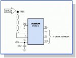
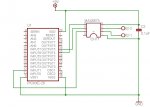
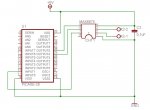
And the schematic is in that pic.
And the "problems":
* should that MAX getting hot? It's burning finger.
* should that code display temp in terminal window correct? Now there shows only nonsense code. In simulation there is temp in lcd screen.
All wiring is ok, but i'll check again. Also I use project board 28/40 for downloading.
I'm going to next add serial lcd, axe033.
The code is which I'm trying to use is from PH Anderson's.
Code:
' MAX6675_1.Bas - PICAXE 28X1
'
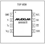
' PICAXE 28X1 MAX6674 / 6675
' CS (term 26) ------------ /CS (term 6)
' SCK (term 25) ----------- SCK (term 5)
' MISO (term 12) <------- SO (term 7)
'
' Uses 155 of 2048 bytes
'
' copyright, Peter H Anderson, Baltimore, MD, Jan , '04
Symbol CS = Output5 ' define terminal associated with MAX6674 / 6675
Symbol SCK = OutPut4
Symbol MISO = Input1
Symbol Val = W0
Symbol WholePart = W1
Symbol FractPart = B4
Symbol Digi = B5
Symbol N = B6
TOP:
GoSub MeasTemp
GoSub DisplayTemp
Wait 1
Goto TOP
MeasTemp:
High CS ' idle
Low SCK
Low CS ' start transmission sequence
Val = 0
For N = 1 to 16
High SCK
Val = Val * 2 + MISO
Low SCK
Next
High CS ' terminate the transmission
Val = Val / 8 ' use only the 13 most sig bits
Return
DisplayTemp:
WholePart = Val / 4
FractPart = Val & $0003 ' two least significant bits
If WholePart > 999 Then DisplayTemp_4 ' Four places
If WholePart > 99 Then DisplayTemp_3 ' Three places
' else ' Two or One places
SerTxD (#WholePart)
Fract:
SerTxD (".")
Branch FractPart, (Fract0, Fract1, Fract2, Fract3)
Fract0:
SerTxD ("00", 13, 10)
Return
Fract1:
SerTxD ("25", 13, 10)
Return
Fract2:
SerTxD ("50", 13, 10)
Return
Fract3:
SerTxD ("75", 13, 10)
Return
DisplayTemp_4:
Digi = WholePart / 1000 ' thousands
SerTxD (#Digi)
WholePart = WholePart % 1000
DisplayTemp_3:
Digi = WholePart / 100 ' hundreds
SerTxD (#Digi)
WholePart = WholePart % 100
Digi = WholePart / 10 ' tens
SerTxD (#Digi)
WholePart = WholePart % 10
Digi = WholePart ' units
SerTxD (#Digi)
Goto FractAnd the "problems":
* should that MAX getting hot? It's burning finger.
* should that code display temp in terminal window correct? Now there shows only nonsense code. In simulation there is temp in lcd screen.
All wiring is ok, but i'll check again. Also I use project board 28/40 for downloading.
I'm going to next add serial lcd, axe033.
Attachments
-
 59.2 KB Views: 67