PhilHornby
Senior Member
My motorcycle is only used sporadically and I know from past experience that lead-acid 12V batteries die from neglect. Buying a dedicated motorcycle trickle-charger seems (relatively expensive) overkill (since I can always use my Bench PSU as a charger) , so I thought I'd go down the 'monitoring' route.
The well regarded "BM2" Bluetooth remote monitor has been dropping in price, because it seems to have some cut-price competition, in the form of the "VGATE 'BM2' Battery Assistant", so I thought I'd start there. It turns out that there is no official "Play Store" app for this - you have to download software from China ...
...
I quickly discarded it, because it draws a constant 15mA - enough to flatten a bike battery in less than a month. Quite why it needs to send a sample every two seconds, I don't know. The app does no long term logging, unless you leave it running continuously.
(With the help of Chatgpt, I managed to write some Python code to interface to this contraption, but that's a whole different story! I still don't know what I can use it for.)
I thought I'd have a go at building my own, Picaxe-based version, which is very simple :-
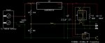
One of the Picaxe 08M2's ADC inputs is used to measure the battery voltage (via a suitable divider) and the resulting reading is sent via the ubiquitous FS1000A 433MHz transmitter. The data format I chose was that used by this Imagintronix Temperature Sensor, to provide a simple standalone display. I have a mini-ecosystem of such devices, so it made sense. You could of course, modify the source to use the method of your choice.
As it stands, there is Picaxe code here to decode it, or you can take the RTL-SDR approach and use the popular RTL-433 software (it decodes as device "39 - WG-PB12V1 Temperature Sensor"). You could even try simply sending the data as ASCII text, if you choose a low baud rate.
The 5V regulator is a low quiescent current type (LM2936). Its data sheet says that capacitor "C1" is essential for 'stability'. I noticed that without it, the output of the regulator was about 9V!!. I was tempted to connect the FS1000A RF transmitter to the "12V" supply, rather than the 5V, for greater range. However, I found a schematic for it and one of the transistors used is rated at an absolute maximum rating of 12V, so I thought better of it.
The Picaxe spends most of its time sleeping and my Bench PSU registers the current draw as 0.000mA, except when transmitting! The acceptable range of input voltages is approx. 4.5V ~ 17.5V.
The correlation between input voltage and ADC reading wasn't quite linear, so the code applies some correction. At first I thought it was just an artefact of the integer arithmetic used, but I later swapped the 08M2 and had to change the algorithm to match. I only need a resolution of 0.1V (and accuracy of less than that), so I didn't get too carried away with this correction.
(As suggested in another thread by @fernando_g, 1% resistors of 30K and 10K for R1+R2 would make the maths easier!)
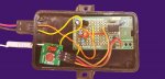
I built the final circuit on a PICAXE-08 Proto Board and shoehorned it into the case of an 'Insurance Company Telematics Black Box' that my daughter gave me.
(You have to rename XT200_Temperature_Sensor.bas to XT200_Temperature_sensor.basinc, since ".basinc" files cannot be attached to forum posts )
The well regarded "BM2" Bluetooth remote monitor has been dropping in price, because it seems to have some cut-price competition, in the form of the "VGATE 'BM2' Battery Assistant", so I thought I'd start there. It turns out that there is no official "Play Store" app for this - you have to download software from China
...I quickly discarded it, because it draws a constant 15mA - enough to flatten a bike battery in less than a month. Quite why it needs to send a sample every two seconds, I don't know. The app does no long term logging, unless you leave it running continuously.
(With the help of Chatgpt, I managed to write some Python code to interface to this contraption, but that's a whole different story! I still don't know what I can use it for.)
I thought I'd have a go at building my own, Picaxe-based version, which is very simple :-
One of the Picaxe 08M2's ADC inputs is used to measure the battery voltage (via a suitable divider) and the resulting reading is sent via the ubiquitous FS1000A 433MHz transmitter. The data format I chose was that used by this Imagintronix Temperature Sensor, to provide a simple standalone display. I have a mini-ecosystem of such devices, so it made sense. You could of course, modify the source to use the method of your choice.
As it stands, there is Picaxe code here to decode it, or you can take the RTL-SDR approach and use the popular RTL-433 software (it decodes as device "39 - WG-PB12V1 Temperature Sensor"). You could even try simply sending the data as ASCII text, if you choose a low baud rate.
The 5V regulator is a low quiescent current type (LM2936). Its data sheet says that capacitor "C1" is essential for 'stability'. I noticed that without it, the output of the regulator was about 9V!!. I was tempted to connect the FS1000A RF transmitter to the "12V" supply, rather than the 5V, for greater range. However, I found a schematic for it and one of the transistors used is rated at an absolute maximum rating of 12V, so I thought better of it.
The Picaxe spends most of its time sleeping and my Bench PSU registers the current draw as 0.000mA, except when transmitting! The acceptable range of input voltages is approx. 4.5V ~ 17.5V.
The correlation between input voltage and ADC reading wasn't quite linear, so the code applies some correction. At first I thought it was just an artefact of the integer arithmetic used, but I later swapped the 08M2 and had to change the algorithm to match. I only need a resolution of 0.1V (and accuracy of less than that), so I didn't get too carried away with this correction.
(As suggested in another thread by @fernando_g, 1% resistors of 30K and 10K for R1+R2 would make the maths easier!)
I built the final circuit on a PICAXE-08 Proto Board and shoehorned it into the case of an 'Insurance Company Telematics Black Box' that my daughter gave me.
(You have to rename XT200_Temperature_Sensor.bas to XT200_Temperature_sensor.basinc, since ".basinc" files cannot be attached to forum posts
)Attachments
-
5.1 KB Views: 4
-
13.8 KB Views: 2
Last edited: