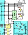
so after finally venturing into mosfets and making my customized rc winch controller which came out much better than expected i have decide to make an alternative board as i can get the size even smaller and with fewer components and via's seeing as now i have a couple of friends who have developed a keen interest in wanting one of my boards.
initially whilst looking around for all in one h bridge solutions i came across several soic8 mosfet h bridge packages, one of which is now the drive of my current board, i also stumbled across another dc driver chip the vishay SI9986 buffered h bridge.
View attachment si9986.pdf
after testing my first design and seeing the current draw was alot lower than i expected under a good load i want to try these chips.
after reading around online i have seen in some chatter that people state that the pins Sa and Sb on the chip can also be utilized potentially by a microcontroller to monitor current.
as this chip would free up 2 pins on my 08m2 i would like some advice how i can do this so i can add a section in my program code to watch either of the pins from the si9986 to stop the winch if its current starts to get within a predetermined range of the chips peak or even max continuous current ratings so as to try and avoid killing it if its held near the motors stall point.
the main reason for this is that this chip does supposedly get warm when running so i dont want to risk exceeding its thermal limits or damaging the sillicon inside if the winch is pushed to hard.
thanks,
tony

