inglewoodpete
Senior Member
I have been contemplating a minimum operating circuit for my PICAXE developments. My current project is a home theatre system controller. Individual routines had been developed using the AXE092 Schools Experimenter (PICAXE 08M).
Few weeks ago I reached a point where I needed to start development with a 28X. I wanted a reliable, standalone, Minimum Operating Circuit [MOC] that I could plug into a breadboard, a development board or a prototype PCB. Other criteria included: (i) easy, reliable programming connection, (ii) a status LED, (iii) a connection point for an optional battery pack and iv) access to the 0v and +5v rails for powering a logic probe.
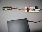
My initial 'support' board or module was created on strip board, although a universal PCB is possible too. The module is connected to an IC socket via a non-removable insulation displacement connector and a short piece of 6-wire ribbon cable. In reality, a PICAXE MOC only requires 4 wires for 8 & 14 pin chips and 5 wires for the larger ones that have a reset pin. I chose to use the 6th wire because (i) I wanted to connect a LED to an output to prove that the PICAXE could run and (ii) I could fit it!
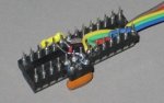
The IC socket is an 'Oupiin' brand, machined-pin socket purchased from Altronics, which is ideal for two reasons. The pins have a 1.5mm long ferrule under the plastic frame allowing wires to be soldered, allowing the socket to double as a plug. The second is that the socket has a cut-out at the ends that can neatly fit 2 layers of 3wires in the form of ribbon cable, which I glued into position. A 100nF capacitor is glued to one side of the socket, its leads soldered to the +5v and 0v pins for electrical stability. A 3-pin section of IC socket is glued to the other side of the main socket for a resonator (pins snipped off at the ferrule after soldering), a requirement for some older style PICAXEs.
The 3 x AA cell battery case, with switch, is available in Australia from Dick Smith. It can be used to provide power to the PICAXE and a breadboard or development board. Alternatively, power to the PICAXE and support board can be provided from the circuit board the module is connected to.
After initially managing to insert the PICAXE backwards (!)*, the unit hasn't missed a beat. *Luckily, the 28X in this configuration is a robust beast. I am considering a PCB version of the module with provision for a 4-way DIL switch to disconnect the various pull-up resistors and/or LEDs when this functionality is provided on the main circuit.
Few weeks ago I reached a point where I needed to start development with a 28X. I wanted a reliable, standalone, Minimum Operating Circuit [MOC] that I could plug into a breadboard, a development board or a prototype PCB. Other criteria included: (i) easy, reliable programming connection, (ii) a status LED, (iii) a connection point for an optional battery pack and iv) access to the 0v and +5v rails for powering a logic probe.
My initial 'support' board or module was created on strip board, although a universal PCB is possible too. The module is connected to an IC socket via a non-removable insulation displacement connector and a short piece of 6-wire ribbon cable. In reality, a PICAXE MOC only requires 4 wires for 8 & 14 pin chips and 5 wires for the larger ones that have a reset pin. I chose to use the 6th wire because (i) I wanted to connect a LED to an output to prove that the PICAXE could run and (ii) I could fit it!
The IC socket is an 'Oupiin' brand, machined-pin socket purchased from Altronics, which is ideal for two reasons. The pins have a 1.5mm long ferrule under the plastic frame allowing wires to be soldered, allowing the socket to double as a plug. The second is that the socket has a cut-out at the ends that can neatly fit 2 layers of 3wires in the form of ribbon cable, which I glued into position. A 100nF capacitor is glued to one side of the socket, its leads soldered to the +5v and 0v pins for electrical stability. A 3-pin section of IC socket is glued to the other side of the main socket for a resonator (pins snipped off at the ferrule after soldering), a requirement for some older style PICAXEs.
The 3 x AA cell battery case, with switch, is available in Australia from Dick Smith. It can be used to provide power to the PICAXE and a breadboard or development board. Alternatively, power to the PICAXE and support board can be provided from the circuit board the module is connected to.
After initially managing to insert the PICAXE backwards (!)*, the unit hasn't missed a beat. *Luckily, the 28X in this configuration is a robust beast. I am considering a PCB version of the module with provision for a 4-way DIL switch to disconnect the various pull-up resistors and/or LEDs when this functionality is provided on the main circuit.
Attachments
-
 67 KB Views: 391
 -
 16.7 KB Views: 372
Last edited:
")