It would be useful if you can determine exactly what the actual input to the controller is. If that is basically an ADC input with thermistor between that and 0V, a pull-up to +5V then you possibly would not need isolation and can inject a voltage directly into the controller using a simple RC as previously suggested. You can then have a fully closed-loop system by monitoring what the voltage being injected is.
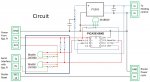
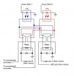
If it is not a thermistor ADC arrangement as above then it gets more complicated; you need the signal isolation, and may only have access to the voltage used to drive the LED-LDR coupler. You could add a second LED-LDR coupler and feed that back via a PICAXE ADC. That signal should reflect any self-heating and illumination related drift back to the PICAXE.
If it is not a thermistor ADC arrangement as above then it gets more complicated; you need the signal isolation, and may only have access to the voltage used to drive the LED-LDR coupler. You could add a second LED-LDR coupler and feed that back via a PICAXE ADC. That signal should reflect any self-heating and illumination related drift back to the PICAXE.
")