MAX232A Capacitors

John Chris

Senior Member
Hi,

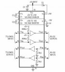
I am using the 18X to drive a MAX232A serial transciever. As I have things set up, however, the picaxe does not like the backwards capacitors (-C --> pin 6, +C --> 0V as well as +C --> pin 2, -C to 5V)

I can not clear the memory of the microcontroller when these capacitors are in place. Why might this be?

In the MAX232 datasheet they suggest 5 capacitors, an additional capacitor (proper polarity) arrangement between supply and ground, whereas this is not shown on pg. 43 of PICAXE manual 3. I'm assuming this is trivial

Is there a reason it is referred to as 0V and not GND? Is this standard notation for circuits involving +/- signals ?

Thanks
 
Last edited by a moderator:

Dippy

Moderator
I really don't know what you mean by "backwards" capacitors??
I may not have the same Data Sheet as you, but the one I'm staring at has all the caps in the right places and the right-way-round. :confused:

If YOU have put the capacitors in the wrong way round then it won't work, the current draw will be high and it'll end in tears. This maybe upseting the PICAXE.

As this isn't working on your circuit, but works for the rest of the electronics industry :), I would suggest (yet) another recheck of your circuit. Do you have a spare MX232 just in case you've damaged yours?

Yes, when you have + and - kicking about you tend to use 0V for clarity. Then, just to confound people, they use Ground too. But that's fine. It's just a reference.

This is from the Data Sheet I have. What's wrong with it? (DO let me know please as I'm worried about my new spectacles from Eway).
 

Attachments

Last edited:

John Chris

Senior Member
Sorry, you're right they're as they should be, I took too quick a glance and thought it was strange to see the positive terminal of the capacitor going to ground. I didn't notice that the negative terminal of the same cap was connected to -10V

I'll recheck ...
 
Last edited by a moderator:

wilf_nv

Senior Member
If the chip really is a MAX232A (with the A suffix) then, according to the datasheet, the charge pump caps should be 0.1uf each. (typically of the non-polarized monolithic variety).
 

John Chris

Senior Member
I'm fairly certain the capacitors are in the right orientation.

To provide regulated 5V to both the PIC and the MAX232 I am using the circuit shown in the attached pdf. Could any difficulties arise due to something in this cicuit
 

Attachments

Last edited by a moderator:

Dippy

Moderator
The plot thickens... switch/mode regulator eh?

So, maybe you've got too much noise and that's upsetting things?

Well, switching regulators are noisier than linear. There's nothing you can do about that.
But, with careful design and using the CORRECT components you can minimise it - but you'l never eradicate it.

I don't know what components you've used. Low ESR caps or something out the back of the drawer?

Below is a diagram commonly used (in format) in S/mode Data Sheets. It shows the 'best' way to layout ground routes to minimise noise.
The thick/bold lines mean 'the shortest/fatest tracks you can manage".

It is also very important that the tracks from Switcher to inductor to O/p capacitor are as short as possible. Any impedance/indutance in the tracks usually introduce noise.
If you get these basics wrong you can use all the capacitors in China and you'll still have a noisy old buck.

You MUST read all the details (and usefully the App Notes too) concerning components. Particularly wrt to Low ESR caps and ceramics - it ain't as simple as some people think.

AND ANOTHER THING:-
1. DON'T put your switcher to near PICAXE.
2. DON'T have any signal tracks under the Inductor
3. Put a (for example) 22nF ceramic cap as close to PICAXE power pins as possible.
4. Maybe even R/C filter the supply to PICAXE.

Got a 'scope?
-No?
Get one.


Any other things in your circuit that you'd like to mention? :)
 

Attachments

John Chris

Senior Member
What 'things' in particular do you figure are being upset?

So I take it, a switch mode LDO regulator is not the most ideal regulator. Is a simple 3 or four pin linear regulator is a better choice for supplying the PIC and a small number of sensors ?

When is a switch mode regulator used?

Attached is the capacitor datasheet.

So PCB layout is rather complicated for this particular regulator. No tracks under inductor. LM2574 - L1 - O/P Cap short as possible ... got it!

22 nF is placed (between supply and ground?) as close as possible to the PIC.

I am hoping to communicate with a sensor whose supply voltage is 6 V. I was thinking that I would have two of these LM2574 regulators in parallel; 5V and 6V. Is this a bad idea?
 
Last edited by a moderator:

Dippy

Moderator
'Things' : I was having a bit of a joke as a S/mode regulator can make big problems.. so I was wondering if there any other 'bombshells' in your circuit that might be equally (potentially) painful for the PICAXE.

OK.

First thing. Capacitors. Oh dear. You need to use LOW ESR (low impedance) capacitors in a Switched Mode. General purpose ones like your link have a higher resistance. Capacitors in a switched-mode design require a number of properties including low impedance and (linked) higher ripple current capability.
So, get LOW ESR capacitors. And CHECK the recommended voltage ratings too!! (DATA SHEET)

Second. Based on that I now have to ask have you used a suitable inductor. Any old lump with the 'right value' will not do. Is the current handling and DC resistance OK. Some baby toroidals saturate too quick and you get funny results. You HAVE to GET the RIGHT ONE as per Data Sheet Spec.

Third. Layout complicated? No, not really, just takes a little care and thought. And this is a case where throwing it into a breadboard is just NOT good enough.

Fourth. "22 nF is placed (between supply and ground?) as close as possible to the PIC."
- yes.


Fifth. "So I take it, a switch mode LDO regulator is not the most ideal regulator. Is a simple 3 or four pin linear regulator is a better choice for supplying the PIC and a small number of sensors ?"
- if you haven't got the gear and/or can't do a good pcb , then if you're in a rush then go for a linear. Having said that, if you have the time to learn then you'll also learn why Sw/Mode regs can, in certain circumstances, pee all over linear. I use them a lot.
But, horses for courses, if you are not using a lot of power and you're not dropping the volts too much then I'd go for linear; easier and smoother.

"When is a switch mode regulator used?"
- Where Sw/mode score is where you are using a fair old current and the voltage drop is a lot. For example: if your circuit was using 500mA at 5V and you were powering from a 12V car battery I'd def go for Switched. They are SOOO much more efficient and therefore stay cooler and are better on the supply. You can work it out yourself. Remember a linear is a 'voltage converter' and a switched-mode is a 'power converter'
With a linear, if you have 500mA at 5V output, you will have 500mA at 12V input (ignoring it's own consumption)
With a switched-mode (and if it were 100% efficient), you'd have 500mA @ 5V output and just over 200mA @ 12V on the input.
So guess which battery will last longer. Guess which regulator will run cooler.

But if you're using 50mA then I'd use linear.
And obv for step-up (boost) regulators they are kiddies to use.
But it is important that the circuit downstream can ignore/reject the extra noise.

"I was thinking that I would have two of these LM2574 regulators in parallel; 5V and 6V. Is this a bad idea? "
Do you really mean parallel? If you do then don't.
Or do you mean one LM2574 to power a 6V circuit and a second LM2574 to power a 5V circuit sharing the same power supply?
If so, that's fine. BUT do remember S/mode will be noisy. If it upsets the sensor (whatever that may be) and you can't get the PICAXE to work because of noise, then forget them. And go for linear. Personally if my sensor only drew a low current I'd go for Linear anyway.

Bloomin 'eck . I've gotta go to the pub.
 
Top