This is one of those cases where Microchip don't put everything on all silicon so unfortunately it's not, as you note, available for the 18M2.
The internal Temperature Indicator Module ( Microchip call it an "indicator" rather than "sensor" ) works by measuring the voltage drop across internal diodes and that varies with temperature but is also affected by voltage and readings vary across chips.
There's a Microchip Application Note (AN1333) which provides much more detail ...
http://www.microchip.com/stellent/idcplg?IdcService=SS_GET_PAGE&nodeId=1824&appnote=en550238
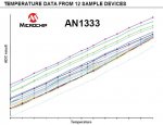
This voltage across the diodes is read using the standard ADC and Figure 4 shows typical readings across the temperature range, -40C to +85C = 120 to 156 (8-bit), = 480 to 624 (10-bit).
So, at 10-bits, that's a reading range of 244 to cover a range of 125C. Calibrated and doing the maths accurately it should theoretically be possible to obtain around 0.5C resolution. Uncalibrated and using the IT_5V0 etc supply voltage indicators in the command and it's accurate to a couple of degree C. However, also take note of Figure 8 - Abs Temperature Error.
Using the IT_RAW command options, calibrating and applying the equations in the datasheet would be the best way for best accurate determination of temperature.
For under and over-temperature detection it can be as simple as "If readValue > N", comparing with a determined level, actual units of measurement not being important.
Whether the internal temperature indicator can replace an external DS18B20 really depends on the project, what resolution and accuracy of temperature is needed, how much effort one's prepared to put in, but it's there if you need it and some projects will likely find it very useful.