Low-Power Battery Backup Reference Design

lbenson

Senior Member
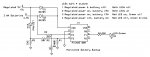
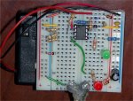
This project implements battery backup (with 3 AAs) to a regulated 5V supply (from mains), with checking of the return of mains supply while running on the battery, and monitoring of the battery voltage through ADC while running on the mains supply.

The original design posted has been replaced with this one to incorporate the suggestions of Mycroft5152 plus some which came to me.

Two LEDs, one red and one green, show the status of the power sources. When both LEDs are on, mains power is on and the battery is showing more than 3 volts (relative to the 5V regulated mains supply). If the battery (which is checked about once an hour) drops below 3 volts, the green LED goes out, showing that the batteries need to be replaced. If mains power goes out the processor clocks down to 31kHz to conserve battery power, and blinks the green LED about once every 7 seconds to show a heartbeat. An additional power-saving feature is the poking of the ADCON0 register to turn off the ADC module while on battery power. The timings are only approximate. The DISABLEBOD command is run upon initialization to reduce current draw and to allow the picaxe to run on very low batteries.

The Green LED uses a 22K series resistor, which makes it faint, but detectable. This reduces power draw when running on batteries. The red LED uses a 2K2 resistor--it is on only when mains power is available.

This is implemented on an 08M, and uses 130 bytes out of the 256 available. It would not be too useful on an 08M because only two I/O lines remains available. On a 14M or larger PICAXE, a good bit could be accomplished with this simple backup circuit.

Many thanks to those who have contributed the ideas for this circuit over the past year and more (nothing about it was invented by me): hippy, dippy, kranenborg, mycroft2152, beaniebots, Dr_Acula, manuka, and others. This seemed to be a good example for drawing a number of threads together.

Enhancement suggestions are invited.

Code:
' 08BakUp2 test battery backup and then battery life

#picaxe 08m
' pin0=AVAILABLE
' pin1=Green LED+22K (battery voltage ok--on while mains on, blinks when off)
' pin2=AVAILABLE
' pin3=sensor for mains--in series 10K, 1n914, 1n914 
' pin4=ADC sensing battery low w. 4K7 (while mains on)
'
' Peek, Poke memory $50-$7f 
'
' LEDs mark 4 states:
' 1  Regulated power, battery off:        Both LEDs off
' 2  Regulated power on, battery>3Volts:  Both LEDs on
' 3  Regulated power on, battery<3Volts:  Red LED on, Green off
' 4  Regulated power off, battery on:     Red LED off, Green blinks
'
' Registers used: b0 (bit0 only), b1 (scratch), b13

symbol mainsOn = bit0
symbol scratch = b1   ' reusable elsewhere for scratch
symbol loopCnt = b13  ' we have a 200ms pause each loop, so 25=5 sec
symbol mainsSensor = pin3
symbol ADCON0 = $1f   ' ADC control SFR register to turn off ADC module
symbol OSCCON = $8f   ' Oscillator control SFR register for speed up/down
symbol ADCtime = $7f  ' counts # of 50 second loops; at 72 (1hr), ADC battery
symbol Red_LED = 0
symbol Green_LED = 1

dirs = %00000011
disableBOD                ' turn off Brown Out Detection for low power
                          ' and because we're doing our own battery monitoring
pause 5000
poke ADCtime,0            ' initialize counter
if mainsSensor = 1 then   ' if we have mains power
  readadc 4,scratch       ' check battery voltage: 3V should be ok
  if scratch > 153 then   ' 255/5v*3v = 153
    high Green_LED
  endif
else                       ' we're starting up on battery
  mainsOn = 1              ' pretend we're coming from a mains-on state
endif
'sertxd("  Restarted ",#scratch,CR,LF)

main:
  do
    if mainsOn = 1 then
      pause 200            ' allow a little debounce time & a little loop time
                           '  Note: instead of pause, "nap" will save
                           '    power, but pwm and servo commands cease
                           '  at 4mHz we will have about 5 loops per second
    else 
'      pause 1              ' we're running at 1/128th the speed on battery
                            ' timings will be based on slow instruction speed
    endif
    if mainsSensor = 1 then ' mains power is on
      if mainsOn = 0 then  ' power is just coming on
        poke OSCCON,%01100000 ' = 4 MHz; speed back up
'        high Red_LED        ' indicate that we have mains power
        mainsOn = 1
      endif
    else                   ' we're running on battery
      if mainsOn = 1 then  ' power just went off
        scratch = b0            ' save bit settings
        peek ADCON0, b0
        bit0 = 0           ' turn off the ADC module to save power
        poke ADCON0, b0
        b0 = scratch
        mainsOn = 0
        low Green_LED      ' can't monitor battery with mains off
        poke OSCCON,%00000000 ' = 31 kHz slow down
      endif
'      low Red_LED          ' turn off mains indicator or turn off blink
    endif
    inc loopCnt
    scratch = loopCnt // 10  ' 10 loops @ 31kHz = 5-7 seconds (experimentally)
    if mainsOn = 0 then    ' we're on battery--give a 128ms flash every 5 sec
      if scratch = 0 then  ' about 5-7 seconds passed (on battery)
        high Green_LED       ' flash led
        pause 1              ' 1*128 = 128ms
        low Green_LED
      endif
    else                   ' we're on mains
'  sertxd("  ",#loopCnt)
      if loopCnt = 250 then   ' about 50+ seconds passed (on mains)
        peek ADCtime,scratch
        inc scratch
        poke ADCtime,scratch
        if b1 = 72 then    ' 250 loops = 50secs * 72 = 1 hour
          readadc 4,scratch       ' check battery voltage 3V should be ok
'  sertxd("  ",#scratch,CR,LF)
          if scratch > 153 then   ' 255/5v*3v = 153
            high Green_LED
          else
            low Green_LED  ' battery needs to be replaced
          endif
          poke ADCtime,0   ' restart 1-hour clock
        endif
        loopCnt = 0
      endif
    endif
  loop
Note that if the system can't do any meaningful work while on battery, the technique often suggested by Dr_Acula might be less trouble--save indicator variables in eeprom (non volatile), and when you restart after a power failure, check those variables so that you can recommence where you left off.

According to my DVM, this setup on batteries takes 31 microamps, blipping up briefly when the LED flashes to between 50 and 155 microamps (the capacitor is taking up some of the slack).
 

Attachments

Last edited:

Mycroft2152

Senior Member
Nice project.

All the cooks here on the forum like to stir the pot a little, here are a few of my 'seasoniongs'.

I am curious why you used 2 diodes on the 5 volt line? if you are looking for a 1.3 volt drop, why not use a red LED and kill 2 birds with one stone?

Also what is the purpose of the R5 pull down resistor on the green LED?

For a further reduction in current, consider the DISABLEBOD command. According to the spec sheet it "significantly reduces cureent during sleep.
 

lbenson

Senior Member
Mycroft2152--All are envited to stir the broth.

>2 diodes on the 5 volt line? if you are looking for a 1.3 volt drop,
>why not use a red LED and kill 2 birds with one stone?

Good idea. And save an output by switching the heartbeat pulse when on battery to the green LED.

>Also what is the purpose of the R5 pull down resistor on the green LED?

That may be an artifact of the process of building. At one point in the debugging process the green LED was dimming significantly but not going off when I expected it to. The 100K pull-down fixed that. I'll go back and try removing it and see if all works now as I expected.

>For a further reduction in current, consider the DISABLEBOD

I knew about DISABLEBOD (thanks to your thread, "Low Power PICAXE 08M - BOD" -- http://www.picaxeforum.co.uk/showthread.php?t=4826 and others), but thought I had read somewhere (can't find it now) that 31kHz trumps that (maybe a reference from Manuka to Brightsparks people). Maybe I got it backwards and DISABLEBOD in conjunction with 31kHz gives the lowest battery usage.
 

lbenson

Senior Member
OK, I found the thread I had been looking for-- http://www.picaxeforum.co.uk/showthread.php?t=6513 -- and had misremembered it. In the last post in the thread, Andrew Bright Sparks NZ said, "[with] DisableBOD ... I managed to keep an 08M alive down to 1uA at 1.3 volts".

I will modify the code to use DisableBOD. This might mean that one could lower the threshhold of 3 volts for the indicator that the batteries need to be replaced, but if the system is to do any useful work, it might need that margin (or more).
 
Last edited:

lbenson

Senior Member
Low-power features

This project uses several techniques suggested in previous posts to reduce power while running on batteries.

1. Run at slower speed. Poke the OSCCON register ("poke $8f,%00000000") to run at 31.250kHz instead of 4mHz (1/128th the speed). See "08M UNDER clocking"-- http://www.picaxeforum.co.uk/showthread.php?t=2233 ; also http://www.kranenborg.org/ee/picaxe/ (search for low-power) also search the forum for "OSCCON".

2. Run DISABLEBOD. This turns off the picaxe brown-out detection, which cause the picaxe to shut itself off at a bit below 3V. With DISABLEBOD, picaxes have been kept alive down to 1.3V. See manuka, et. al.: http://www.picaxeforum.co.uk/showthread.php?t=6513 ; also Mycroft2152, "Low Power PICAXE 08M - BOD" -- http://www.picaxeforum.co.uk/showthread.php?t=4826

3. If you are using occasional ADCs while on battery, turn off the ADC module between reads by poking the ADCON0 register ("poke $1f,value"). Bit0 of value turns it off, but the register should be read first so that other bits are preserved. See Dippy "So for low-power people (doing the occasional A/D) it looks like a quick poke might be in order to switch off ADC module" http://www.picaxeforum.co.uk/showthread.php?t=5950 ; also http://www.picaxeforum.co.uk/showthread.php?t=8346

4. Pull down all unused inputs to 0V, e.g. with 100K or even 1M resistors. See "problem with getting very low power consumption" http://www.picaxeforum.co.uk/showthread.php?t=2292
Kranenborg: After I had tied all 18X inputs low current consumption dropped from a very unstable 250 uA to a very stable 30uA at 5V and 31kHz (equiv. current consumption at 4MHz is approx 1.5 mA = 1500uA thus meaning a reduction to only 2% of the original consumption).
5. Current-limit any outputs to the degree possible. For example, at 4.5V, an LED with a 330 ohm resister uses about 13 milliamps. With a 22K2 resister it is much dimmer, but readable, and uses only .2 milliamps. Blink patterns can further reduce current usage while expanding the information provided.

For any register poking, confirm on the Microchip datasheets that you are poking the correct register for that chip.
 
Last edited:

Mycroft2152

Senior Member
5. Current-limit any outputs to the degree possible. For example, at 4.5V, an LED with a 330 ohm resister uses about 13 milliamps. With a 22K2 resister it is much dimmer, but readable, and uses only .2 milliamps.
LEDs have different efficiencies and brightness levels. It used to be that LEDs needed between 10 and 25 millamps to be seen, thus the standard 330 ohm resistor for a 5 volt source. Unfortunately most of the hobby surplus LEDs fit into this catagory.

Recently, I bought a string of multicolor christmas tree LED lights, ($7US with 70 LEDs), just for a source of LEDs. I was very surprised to find that they were both super bright and super efficient. I was able to run the Blue LEDs at 5 volts with a 100K resistor and still get a decent indicator. The other colors were not as efficient, but still ran fine with 22k resistors.

As Ibenson says, for battery powered devices, minimize the output current to extend the useful battery life.

IB, good summary of the tricks to minimize power requirements.
 

adumas

Member
Testing

Hi... I built the circuit as you laid it out (multiple times) and input the program.

I don't seem to be able to ever get a solid green light... It always blinks - no matter if I supply 4.5v or less.

With my multimeter I detec 4.55v going to pin 3 and 0v at pin 6.

Has their been a revision? Is this circuit working?

It is the ideal project and I would really like for it to work...

Any help would greatly be appreciated.
 

lbenson

Senior Member
I thought I had posted a response to this question earlier--maybe didn't press the final post button. Yes, the circuit is working, and hasn't been modified since about December 10, 2007. I actually disconnected the mains wall wart to see how long the battery would last on low power, and it has been blinking away every seven seconds for 10 months now on 3 AAs. Can you post a photo of your circuit?
 

tiscando

Senior Member
If the battery-backup module is connected to mains, and the green LED is still flashing, then you may have put in a flashing LED.
 

lbenson

Senior Member
It's now been over a year since I posted this little project--to run an 08M at low power on backup from batteries when disconnected from mains. It has been disconnected for 12 months, running off of 3 AAs, and continues to blink its green LED every 7 seconds. That's about four and a half million blinks. The battery voltage reads 4.26 volts. This is a testimony to how power-efficient the picaxe can be.
 

lbenson

Senior Member
This is now the 2-year anniversary of the posting of this project and it's disconnection from the mains power pack. The green led is still blinking away every 7 seconds on the original 3-AA battery pack--over 2 million blinks. The battery voltage reads 4.18 volts, down from 4.26 volts about a year ago. Amazing how the picaxe can just sip current while waiting for something to happen. Waiting ... waiting ....
 

stocky6409

Senior Member
I'm going to have a play with adding some of this code my one of my current apps (pardon the pun!)

Size is a a factor and while its happily running from 3 x AA 700mAh nicads i need to make the batteries smaller so want to try and go down to AAA or N cells - but need to make some power savings along the way!

I'm going to have to do some code optimisation tho i think as i am already at 240 or 256bytes in my 14M!

Stocky
 

lbenson

Senior Member
It is now past the 3-year anniversary of the posting of this project and the green led is still blinking away every 7 seconds on the original 3-AA battery pack--over 3 million blinks. Go 08M!
 

techElder

Well-known member
It's your project and a monument to low battery consumption, but what's the point of all this if you aren't really doing anything but blinking the LED? There are plenty of transistor circuits that will blink an LED for a VERY long time.

From what I can tell, you are only testing how long the 08M can blink an LED on the backup battery and are probably only testing the shelf life of the batteries themselves.

So, what? The battery people already give us some idea what that is.

Ok, it still works ... that's something, but dang I thought that was something after a year of working.

What's the point now? (Just trying to figure out what you are accomplishing.)
 

hippy

Technical Support
Staff member
I might be easily amused but it makes me happy. I had a little "whoop" at hearing it's achieved 3 years.

I think it falls into the "Keith Richards" category; remarkable that it's still alive and performing well :)

For a more serious answer : I think the main benefit is as a reference design, really pushing the limits. One year proved a lot but I for one am intrigued as to when it does conk-out in the future. We get a lot of theory, make a lot of educated guesses, on battery life and expectations and just how low a PICAXE can go but don't often get to see how those match reality long term.

I think in terms of people asking, "Can a PICAXE really run from a set of batteries for X years?", here's the answer, and there's a lot of value in that.
 
Last edited:

Dippy

Moderator
I think that's a great result - and proves something is possible.

My own low-power contribution is an 18X based hand-held Data Extractor using the dual-MOSFET p/b switch PICAXE-latch-on design.

My apologies to Stan :) , but that is still working after 3 years and uses an Alkaline PP3 (shi*, I swore!!. Apologies to the 3xAA fraternity).

In my case, I have shown that a hand-held device with push-button switches can be made and only requires a couple of semis and a couple of resistors.
In fact the whole switch control could be on a square cm or two with SMD.

Ibenson has demonstrated long battery life in operation.
What use is it?
I can think of several Apps.
1. A weather station temp/humidity sampler plus RF.
2. An RF receiver with low duty.
3. A voice synthesiser which reminds you , once a day, to read the Data Sheets.
4. A break-beam or reflective sensor for lighting or security.
..... use your imagination.... anything that needs to be done now and then.


These designs are pretty simple to old lags who actually know things about electronics, but newbies and some die-hards can't get their heads around the possibilities. Experiments like this show what can be done with a healthy brain and careful design.

Good stuff.
 

lbenson

Senior Member
Texasclodhopper--the device wasn't intended to perform any task, though with RF it could be an alarm testing for some condition (as it currently tests for return of mains power, which I doubt it will ever see).

I did it because there were a number of different threads which addressed aspects of the low power issue, but did not draw them all together. In post 5, I referred to posts of others who had done original research. These techniques are still applicable to the 08M, but not every one of them (for example, low clocking) may be for newer chips, which, I understand, do a better job of powering down during sleep.

Giving notice once a year that it still has a heartbeat seems to me not to be excessive bumping.
 

NXTreme

Senior Member
It's also a part of the Picaxe forum's history. If lbenson pulls the plug on this it'd almost be like taking life support off of a person in a coma. They might not be doing anything but you never know when they're gonna wake up. And think of the blinking LED as the heart rate monitor :). I for one want to see this thing going for as long as possible.
 

techElder

Well-known member
You all totally misinterpreted my post.

Of course it's a legend and of course it doesn't take up any space here on the forum. Of course it COULD do the whole bunch of things that you enumerated.

I didn't say that it wasn't or wouldn't or couldn't.

What would make this interesting is if it was actually DOING something instead of just showing how long a set of batteries can last without a load on them.

Your project is just there. It doesn't even keep the time.

I suppose that's enough. :eek:
 
Last edited:

Dippy

Moderator
Ah, I see.
But, if we ALL misinterpreted your post what does that tell you?
A) We are all incapable of reading.
or ,
B) .... fill in here ... :)

Anyway, all clear now.
But I think it should be fairly common sense that where we have CODE=Flash LED we could insert anything we wanted . It should also be fairly obvious that what we insert will affect the lifetime.

But what has been shown - and we are ALL I agreed I should hope - is that with some care / skill it is POSSIBLE to have very low power circuit.

I'll leave you all to discuss for another 10 pages. I've got to go to the Bat Cave.
 

lbenson

Senior Member
Here's the year-4 anniversary update. The green led is still blinking away every 7 seconds on the original 3-AA battery pack--over 4 million blinks now. The battery reads over 4 volts--very little drop in the past two years.
 

hippy

Technical Support
Staff member
Excellent news and it really is going to be a sad day when it finally expires.
 

Janne

Senior Member
hmmm 4900+ views on this thread.. I think you should jnstall a webcam to stream the blinking online :D
Extra points to the one who spots the last blink of the dying battery.
 

pleiser

Senior Member
you should compare it to a circuit doing the same thing without power saving techniques, and see how long it lasts.
 

lbenson

Senior Member
>you should compare it to a circuit doing the same thing without power saving techniques, and see how long it lasts.

Exercise left to any interested party. ;-)
 

lbenson

Senior Member
Yesterday was the 5th-year anniversary of the posting of this project. I looked at it--still blinking away every 7 seconds on the original 3-AA battery pack. I earlier misrememberd the number of blinks in a year (# of seconds / 7). It's about 4.5 million blinks a year, or over 22 million blinks so far.

Battery voltage measured with my cheap DVM was 4.01 volts.

Considering what Andrew Bright Sparks NZ said--"[with] DisableBOD ... I managed to keep an 08M alive down to 1uA at 1.3 volts"--there may be a lot of life left in this. 4.01V is down from 4.26V when I started--I didn't think to begin with fresh batteries.
 
Last edited:

lbenson

Senior Member
The 6th-year anniversary of the posting of this project passed over a week ago. It's still blinking away every 7 seconds on the original 3-AA battery pack--over 26 million blinks so far.

Battery voltage is 3.98 volts, barely down from last year's 4.01 volts.
 

hippy

Technical Support
Staff member
Once again congratulations on its longevity. I am beginning to suspect that, one day, we will all be gone, leaving a PICAXE in space shouting out its message and a PICAXE blinking in the dark.
 

srnet

Senior Member
Once again congratulations on its longevity. I am beginning to suspect that, one day, we will all be gone, leaving a PICAXE in space shouting out its message and a PICAXE blinking in the dark.
The PICAXE in space flashes its LED too.
 

lbenson

Senior Member
The 7th-year anniversary of the posting of this project has passed. It's still blinking away every 7 seconds on the original 3-AA battery pack--around 30 million blinks so far.

Battery voltage is 3.89 volts.
 

techElder

Well-known member
Not yet. At the rate the battery is depleting, I expect at least a few more years.
What would have been nice is to have the same battery sitting side-by-side with it. Then you would know what is going on compared to just plain battery droop over time.
 

lbenson

Senior Member
What would have been nice is to have the same battery sitting side-by-side with it. Then you would know what is going on compared to just plain battery droop over time.
If I had had even the remotest notion that it would still be running, and the thread might be active (minimally), seven and a half years later, I should have done that, and even started with fresh batteries.
 

newplumber

Senior Member
I'll put my vegetables in the pot i mean rocks and rutabagas
I've read this post from start to finish It has to be the funniest one I've seen especially the web cam idea :)
and the texasclodhoopers ingredients taken to serious
I think its all in great fun to stir the pot in every 7 seconds
lbenson thanks for doing this project and I wont cry when it dies but its awesome to know
 

lbenson

Senior Member
Hey, newplumber, we had rutabaga (turnip in Canada) 3 nights ago in our turkey stew. Left out the rocks, though--what variety do you prefer for flavor or texture?
 
Top