bfgstew
Senior Member
OK Nick got me in the right direction with character mapping, but now the code is a scource of trouble.
I am after having a linear scale along the bottom of my 20 X 4 OLED, using a 10K pot and readadc on A.1
Each block on the screen is made up of 5 segments, so in total there are 100 segments, this unfortunately gives a sum of 2.5 per segment as variable is 0 - 255, so 255 / 100 = 2.5 Picaxe doesn't do fractions, so how can I get over this small hurdle?
The code I have been working on, gives me the blocks on the bottom row, but not how I want it. I would like to have it so when the pot is rotated to the right, the scale goes along the screen, rotate pot to the left, scale goes back along the screen.
The code so far - I have only worked on 4 blocks as the code looks like it will be faily lengthy, unless some kind soul can show an easier way?
Code:
#slot3
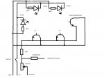
; picaxe 28x2
symbol SOUND_ON = C.0
symbol CAMERA = C.1
symbol FLASH = C.2
symbol SOUND_IN = A.3
symbol LIGHT_ON = C.4
symbol PG_ON = C.5
symbol TIMER_LED = C.6
symbol READY_LED = C.7
symbol LIGHT_IN = A.0
symbol PG_IN = A.1
symbol SOLENOID = A.2
symbol COL2 = pinB.0
symbol ROW1 = B.1
symbol COL1 = pinB.2
symbol ROW4 = B.3
symbol COL3 = pinB.4
symbol ROW3 = B.5
symbol ROW2 = B.6
symbol DROPS_LED = B.7
serout C.3, N2400, (254,1)
pause 50
high PG_ON
do
readadc A.1,b3
if b3 <= 3 then
serout C.3, N2400,(254,212)
serout C.3, N2400, (0) endif
if b3 =< 5 then
serout C.3, N2400,(254,212)
serout C.3, N2400, (1) endif
if b3 =< 7 then
serout C.3, N2400,(254,212)
serout C.3, N2400, (2) endif
if b3 =< 10 then
serout C.3, N2400,(254,212)
serout C.3, N2400, (3) endif
if b3 =< 12 then
serout C.3, N2400,(254,212)
serout C.3, N2400, (4) endif
if b3 =< 15 then
serout C.3, N2400,(254,212)
serout C.3, N2400, (4)
serout C.3, N2400,(254,213)
serout C.3, N2400, (0) endif
if b3 =< 18 then
serout C.3, N2400,(254,212)
serout C.3, N2400, (4)
serout C.3, N2400,(254,213)
serout C.3, N2400, (1) endif
if b3 =< 20 then
serout C.3, N2400,(254,212)
serout C.3, N2400, (4)
serout C.3, N2400,(254,213)
serout C.3, N2400, (2) endif
if b3 =< 23 then
serout C.3, N2400,(254,212)
serout C.3, N2400, (4)
serout C.3, N2400,(254,213)
serout C.3, N2400, (3) endif
if b3 =< 25 then
serout C.3, N2400,(254,212)
serout C.3, N2400, (4)
serout C.3, N2400,(254,213)
serout C.3, N2400, (4) endif
if b3 =< 27 then
serout C.3, N2400,(254,212)
serout C.3, N2400, (4)
serout C.3, N2400,(254,213)
serout C.3, N2400, (4)
serout C.3, N2400,(254,214)
serout C.3, N2400, (0) endif
if b3 =< 30 then
serout C.3, N2400,(254,212)
serout C.3, N2400, (4)
serout C.3, N2400,(254,213)
serout C.3, N2400, (4)
serout C.3, N2400,(254,214)
serout C.3, N2400, (1) endif
if b3 =< 33 then
serout C.3, N2400,(254,212)
serout C.3, N2400, (4)
serout C.3, N2400,(254,213)
serout C.3, N2400, (4)
serout C.3, N2400,(254,214)
serout C.3, N2400, (2) endif
if b3 =< 35 then
serout C.3, N2400,(254,212)
serout C.3, N2400, (4)
serout C.3, N2400,(254,213)
serout C.3, N2400, (4)
serout C.3, N2400,(254,214)
serout C.3, N2400, (3) endif
if b3 =< 38 then
serout C.3, N2400,(254,212)
serout C.3, N2400, (4)
serout C.3, N2400,(254,213)
serout C.3, N2400, (4)
serout C.3, N2400,(254,214)
serout C.3, N2400, (4) endif
if b3 =< 40 then
serout C.3, N2400,(254,212)
serout C.3, N2400, (4)
serout C.3, N2400,(254,213)
serout C.3, N2400, (4)
serout C.3, N2400,(254,214)
serout C.3, N2400, (4)
serout C.3, N2400,(254,215)
serout C.3, N2400, (0) endif
if b3 =< 42 then
serout C.3, N2400,(254,212)
serout C.3, N2400, (4)
serout C.3, N2400,(254,213)
serout C.3, N2400, (4)
serout C.3, N2400,(254,214)
serout C.3, N2400, (4)
serout C.3, N2400,(254,215)
serout C.3, N2400, (1) endif
if b3 =< 45 then
serout C.3, N2400,(254,212)
serout C.3, N2400, (4)
serout C.3, N2400,(254,213)
serout C.3, N2400, (4)
serout C.3, N2400,(254,214)
serout C.3, N2400, (4)
serout C.3, N2400,(254,215)
serout C.3, N2400, (2) endif
if b3 =< 47 then
serout C.3, N2400,(254,212)
serout C.3, N2400, (4)
serout C.3, N2400,(254,213)
serout C.3, N2400, (4)
serout C.3, N2400,(254,214)
serout C.3, N2400, (4)
serout C.3, N2400,(254,215)
serout C.3, N2400, (3) endif
if b3 =< 50 then
serout C.3, N2400,(254,212)
serout C.3, N2400, (4)
serout C.3, N2400,(254,213)
serout C.3, N2400, (4)
serout C.3, N2400,(254,214)
serout C.3, N2400, (4)
serout C.3, N2400,(254,215)
serout C.3, N2400, (4) endif
; CGRAM addressing for segments and block
serout C.3, N2400, (254, 64, 48, 48, 48, 48, 48, 48, 48, 48) ; 1st segment = (0)
serout C.3, N2400, (254, 72, 56, 56, 56, 56, 56, 56, 56, 56) ; 1st and 2nd segment = (1)
serout C.3, N2400, (254, 80, 60, 60, 60, 60, 60, 60, 60, 60) ; 1st, 2nd and 3rd segment = (2)
serout C.3, N2400, (254, 88, 62, 62, 62, 62, 62, 62, 62, 62) ; 1st, 2nd, 3rd and 4th segment = (3)
serout C.3, N2400, (254, 96, 63, 63, 63, 63, 63, 63, 63, 63) ; whole block = (4)
loop
Last edited: