Line-follower-2nd bot

sbscott

Senior Member
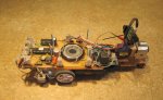
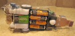
Building bots is addictive. The more you do, the easier, more fun it is! This guy is the basic line follower chassis. I am waiting to mount a very small wireless video cam (not delivered yet) to mount on top with an avoidance senor as well. But, it works!


http://www.youtube.com/watch?v=CRlIw6huYbU
http://www.youtube.com/watch?v=YiM9Sp6nNHE

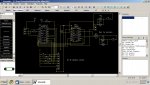
I have attached the schematic and the rough code.

Any suggestions (code) to make the bot do course correction more smoothly?
 

Attachments

BeanieBots

Moderator
Building bots is addictive.
Hmm, must admit to that affliction too;)

I thought your line following was quite good as it is but if you want to improve things, there are two approaches you can take.

One is simply to put the sensor closer to the drive wheels which will reduce the overall control loop gain.
The other method is to use the sensors in an analogue mode to indicate how far from the line you have drifted and then apply an appropriate correction (PWM motor drive) rather than a hard on or off.
If you are already doing that, then reduce your response gain and or make it non linear.
 

sbscott

Senior Member
Ahhhh, PWM... I am looking at the manual and am not sure how to approach using this function. The example in the manual. It looks like pins 9,11,12,13 are for this function on the 18M2.

"init:
hpwm 0,0,%1111,150,100 ‘ start pwm
main:
hpwmduty 150 ‘ set pwm duty
pause 1000 ‘ pause 1 s
hpwmduty 50 ‘ set pwm duty
pause 1000 ‘ pause 1 s
goto main ‘ loop back to start"

I don't see where you identify the pin on the 18M2?
Maybe a short sample example:)
 

eclectic

Moderator
Ahhhh, PWM... I am looking at the manual and am not sure how to approach using this function. The example in the manual. It looks like pins 9,11,12,13 are for this function on the 18M2.
snip
I don't see where you identify the pin on the 18M2?
Maybe a short sample example:)
See Manual 1, page 32

And, in the PE

PICAXE > Wizards > Pwmout

e
 

hippy

Technical Support
Staff member
Also the 18M2 supports PWM through the PWMOUT command, not HPWM.
 

sbscott

Senior Member
I also see that my manuals are out dated. So I will get the new ones.

So, that means there are only two pins on the 18M2 that can be used for PWMout, is this correct?

I guess I am still confused as to how these pins are used. For a DC motor, you need two of these pins to allow it to turn forward and reversed?
 

eclectic

Moderator
For testing:

This program works,
changing the intensity of two LED's.

I've used 10kHz for both, but your motor
may need a different frequency.

I've deliberately left it UN-commented,
so that you can explore the Wizard. :)

And also, the Simulation is another way to
find your way around the pins.

Code:
#picaxe 18M2

pwmout B.3, 199, 0  ;10kHz 
pwmout B.6, 199, 0

pause 2000

main:

pwmduty B.3,  400
pwmduty B.6,  400

pause 2000

pwmduty B.3,  800
pwmduty B.6,  800

pause 2000

pwmduty B.3,  100
pwmduty B.6,  100

pause 2000

goto main
e
 

hippy

Technical Support
Staff member
I guess I am still confused as to how these pins are used. For a DC motor, you need two of these pins to allow it to turn forward and reversed?
If you want to drive a motor you put two digital on-off signals into a H-Bridge ( L293D or similar ) and then you use those signals as a pair to allow forward, reverse and stop. That gives you single speed forward or reverse. You need a pair of signals for each motor if you have two ( most bots and buggies will have two ).

If you want to add speed control you also put PWM into the H-Bridge which allows the speed of the motor to be controlled. The wider the pulse the faster the motor. You can use one PWM and have two motors controlled by a single PWM ( the speed of each changes together ), or you have two PWM one per motor and have independent speed control.

So for a fully speed controlled motor there will be a pair of signals (forward, reverse and stop) plus a speed control (PWM) signal.

There are various ways these can be combined to require less signals per motor but these are refinements of the basic idea. For example if PWM can set the speed or stop a motor, you only then need a single other signal to indicate to go forward or back when it's not stopped.
 
Last edited:

sbscott

Senior Member
Thanks a bunch...I will have to spend some time sorting this out and may have an additional question or two!
 

sbscott

Senior Member
Ok, I have my manuals updated and have reviewed the PWM, PWM Duty, and the PWMOut commands and I think I have basic understanding..

Now, HIppy said,
If you want to add speed control you also put PWM into the H-Bridge which allows the speed of the motor to be controlled. The wider the pulse the faster the motor. You can use one PWM and have two motors controlled by a single PWM ( the speed of each changes together ), or you have two PWM one per motor and have independent speed control.

So for a fully speed controlled motor there will be a pair of signals (forward, reverse and stop) plus a speed control (PWM) signal.
I just don't see this. "put PWM into the H-Bridge" What does this mean? I am trying to see a schematic of this but it ain't happening!

I have eclectic's code running with a set of LEDs and I see the changes. But, like I said, I don't see how this fits with using the the L293D.
 

eclectic

Moderator
A serious suggestion:
If Sparkfun or Peter Anderson stock the
very latest 28X2,
then you have four separate Pwmout channels

A version of the diagram in M.2, p.13 would give
full speed control (F+R) of two motors.

e
 

sbscott

Senior Member
Ok, getting there! Got both motors moving in both directions at different speeds! Will have to figure out exactly what I am seeing but it should help stabilize the bot. Once I have it redone, I will repost the code.

Thanks again!
 

sbscott

Senior Member
Well, after much effort and frustration, I have gone with the 28x2 and have wandered away from PWM. Could not control the motors, servo and other things effectively. I have also drifted back to the object-avoidance bot and have added extra features including a video cam, audio sounds, a drop-off sensor and remote swt control to force the bot to turn around when it gets into trouble. I will post pics, video and schematic tomorrow.

I will get back to the line following when have I mastered this fellow:)
 
Top