Light Monitoring Circuit

SKL BOI

Member
Hi

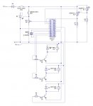
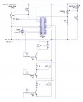
I an planning on making a light monitoring circuit that then changes the light levels to a pre specified level. I will create a prototype board first at 12V then move up to a 240V final board.

I am using a 28X2 picaxe Chip Could you please check to see if i have missed anything on my circuit diagram?

Thanks

SKL BOI
 

Attachments

BeanieBots

Moderator
A pull-up on RESET would help.

What is the purpose of the LED & POT?
What does the calibrate button do and how? (besides popping D8 when pushed)
We can only guess if those are OK.

240v lights with a 12v supply.
Will your 240v supply be DC?
How will you switch 240v? Not with an open collector signal tranistor I hope or do you have the correct type?

I'll let somebody else to start the debate on decoupling capacitors.
 
Last edited:

Dippy

Moderator
How about some decoupling on PICAXE +/0V?

That thing; is it a resonator or a crystal?
If res; no ground shown.
If crys: then needs caps.

Are they really 240V light bulbs?
 

SilentScreamer

Senior Member
I guess that circuit is made with livewire? If so then there is no resonator component in the software but when making the circuit you need to take the centre pin down to 0V. I used to add a one pin terminal and place it so it in the middle to prevent confusion.
 

hippy

Technical Support
Staff member
As noted D9 is wrong way round, and there's no need for it anyway.

Not sure what value the XTAL actually is or what speed you want to run the X2 at, but the chip includes a PLL which multiplies the external XTAL by four; 4MHz XTAL will give 16MHz operation (EM16), 8MHz XTAL will give 32MHz operation (EM32), 10MHz XTAL will give 40MHz operation (EM40). That should also be a three-pin resonator, or if a two-pin resonator or crystal it will need capacitors to 0V.
 

SKL BOI

Member
Hi

Thanks for all getting back so quickly.

Sorry about the 12v 240v confusion i was as usual doing lots of things at once.

The resonator yes i will be using a 3 pin resonator but as you say live wire doesn't have it in there this is my first diagram and i do normally do as you said and add a pin down to zero volt.

SO if i use a MHz resonator it will multiply it up to 40 as picaxe specify's?

Thanks about the D9 diode direction.

I have added a reset thanks i forgot about that.

I thought that if i use a 250V NPN Transistor that it would work.

Obviously i am going to be using the PWM so as long as they are on the right pins (please Confirm).

What is decoupling? (Sorry)

Thank you very much

SKL BOI
 

MartinM57

Moderator
I thought that if i use a 250V NPN Transistor that it would work.

Obviously i am going to be using the PWM so as long as they are on the right pins (please Confirm).
So what exactly are these 'lights' - 250v filament lamps running off AC mains?

If so, you're unfortunately on the wrong track to use a simple "250V NPN transistor and PWM (of course)"
 

BeanieBots

Moderator
For decoupling, see this:-
http://www.interfacebus.com/Design_Capacitors.html

Switching the 240v lights:-
Where does the 240v come from? Is it mains?
If it's mains, then the supply will be AC and a transistor won't work.
Nor will PWM control.

If it's not mains and you have a 240v DC source (from somewhere) then what power rating are they? Will your transistors cope with the cold-start surge current?

If you are not sure about some of these aspects, do you think you should be playing with voltages that can KILL?

Also, if you are thinking of connecting your circuit to your domestic wiring, do you know the legislation and what you can and cannot do legally?
 

Dippy

Moderator
STOP!!!!!!
Do not connect this to 240V Mains.

You obviously don't know enough about this so stop right here and get PROPER advice!!!

Bang away at 12V by all means.

And the dcoupling as I metioned is putting a capacitor across the PICAXE power pins.
A) It reduces noise getting into PICAXE
B) It can improve the ADC behaviour.

Have you absorbed the warning ref the LED?
 

SKL BOI

Member
Yep i haven't started yet!

Do you mean the LED in between the switch and the Potentiometer?

What do i need to know what is wrong with how I'm trying to do it?

Ok thank you

SKl BOI
 

Dippy

Moderator
Is there another LED? I'm afraid I can't see it.

It's not 'in between' (electrically) the switch and pot. It's in parallel. It has NO current limiting resistor. Have a read of an LED Dat Sheet to see the maximum current your LED can stand - and then knock a bit off to play safe.
20mA is typical for a cheapo. A high brightness red one would work well at 5mA.
Without some kind of current limiting it will POP when you press your button.

So you need to add a series resistor. The value of which you can easily calculate - or get someone to calculate for you.

You cannot safely switch mains AC with a simple transistor. And it worries me that you'll try it.
Have a read up on Triacs and things like that.
Things are NEVER as simple as they look in your school books.
Transistors can NOT be directly compared to a mechanical relay.
 

BeanieBots

Moderator
Let's forget about the mains side of things for now because you are NOT GOING TO DO IT right?

So, how many LEDs are there on your circuit?
I can only see one. The one everyone has mentioned that will pop when you push the button.
As asked earlier, what is the button MEANT to do?
Then we might stand a slight chance of knowing if your circuit can do it.
At the moment, pushing the button will result in destruction.

Let's get the simple task of driving the LED right before we move onto the more complex stuff.

So, tell us. What should happen?

EDIT:
It might also be a good idea to explain YOUR reason for D9 and what the POT is for.
Also, so that we have the WHOLE picture, please explain how and where your 5v and 12v supply lines will come from. I have a wager that they not as simple or straight forward as you think they are.
 
Last edited:

SKL BOI

Member
Ok ill forget about the mains side i agree we should get it working in 12v first!

I'm reading up on mains voltage stuff now

I've updated the circuit diagram

I want to have a "light monitor" that will take the average between 2/3 LDR inputs and then control a maximum of 3 house hold lights (final version).

Thanks
 

Attachments

SilentScreamer

Senior Member
Do you need to have variable control over the 240V lighting? I.e. does it need to fade in any way? If not then you could use relays which would be the easiest way for 240V mains control, but get it working with 12 first.

EDIT: You are still missing decoupling capacitors. It needs to be a capacitor across the PICAXE's +V and 0V rails and ideally as close to the chip as possible. More experienced members can offer better advice than I can on types and values of capacitor.
 
Last edited:

MPep

Senior Member
You do not need diodes across the lamps.
Diodes should be used when using relays, however.

With the 12V circuit, I cannot see any problems. Well except for decoupling capacitors. Use something like 100nF across + and -, close to the PICAXE.
 

MartinM57

Moderator
If your just going for a 12v solution...(your circuit WILL NOT just scale up to 240v mains without an almost complete redesign - but you're never going to build a 240v version are you?)...

...drop the diodes across the lamps (no need for them at all)

...as above, please explain where the 5v and 12v supplies are coming from

...why the switch in the supply line - you usually switch the power supply, not just the processor

...R7 and R8 look the wrong value. Do the potential divider calculations using the extreme values of NORPS-12 resistances in the light and dark (look at the data sheet on the Rapid web site). Can you see why 1K isn't the right value?

..why not build the download circuit into the design - you're going to get very bored taking the PICAXE out and in to a development board

...What frequency is the resonator - it can't be both the ones you show!
 

nbw

Senior Member
don't forget the decoup caps... think of them as shock absorbers for when your power supply hits a bump or a dip :)
 

kevrus

New Member
If anyone would like to see a horrific video depicting the dangers of electricity, then drop me your email address (its not for the squeemish). Admittedly it's above 240v, but it should get the message home. I got sent this from a fellow electrician, not sure were he got it from.
 

nbw

Senior Member
is that the one where the guy on the train in India decides to touch the overhead cables? That's a real eye-opener. Awful.
 

Andrew Cowan

Senior Member
I really don't think you can safely deal with 240v. However, if you find someone who knows why they are doing, and can supervise you, I would use an optocoupleing setup by PWMing an LED which is next to an LDR on a light dimmer. But don't do this on your own - get some supervision!

A
 

Dippy

Moderator
Andrw: Yes, that was exactly how someone else did it recently wasn't it. Cheap light dimmer, swap pot for LDR and fire an LED at it.
Based on what I have read so far, I suggest SKLBOI gets someone experienced to do this part.

I agree with Martin, R7 and R8 look like guessed values.
As some of schematic idents look at bit random I can only suggest that you get some LDRs and bread-board them with different value fixed resistors.
There is a huge range of LDR light vs resistance response.
Some dark resistance values are huge and may give you some very odd ADC results.

So, SW3 is now a reset.

Still no decoupling caps on PIC.
SKL BOI it's simply a capacitor (or two) across the PICAXE power supply pins... nothing mystical.
If you have PWMs and noise buzzing around a circuit then decoupling is important. And much more so if doing ADC.
 

SKL BOI

Member
Ok thanks

Ill make those changes.

I think that i should stop this until i see my teacher next and look through it all then and figure it out with her as obviously i need to learn allot more with mains voltage.

Thanks ill carry on with this once ive advanced.

SKl BOi
 

bgrabowski

Senior Member
No school or examination board in the UK will permit a student to undertake a project which uses mains electricity.

Keep to 12V DC for the practical work and perhaps suggest in your evaluation how the circuit could in theory be used to switch the mains eg by using relays.
 
Top