Hi,
Electrically, the voltage rating of a capacitor is not very important, provided that it is "high enough". So in principle a PICaxe circuit could use 6.3 volt electrolytcs (but there can be minor disadvantages). A parameter of capacitors that we haven't really discussed is their physical size (often called the "can" size). The (volumetric) size of the can is approximately proportional to the product of the capacitance and the voltage rating (or the C.V product). Typically, a capacitor of 10uF at 16v (or 16uF at 10v, etc.) is about the smallest physical size that's worth manufacturing. Generally, a manufacturer's capacitor family may have about 6 can sizes covering about 10 - 100 uF at 16v. So the 100uF may have about 8 times the volume of a 10uF, i.e. twice the linear dimensions, but probably increasing more in diameter than in height. If physical size is an important factor then you might consider lower voltages (when practical) of 10v, 6.3v , 4.0v or even 2.5 volts, but probably not unless values above 100 uF are required.
Conversely, if lower capacitor values are needed (to respond more quickly as you say), you might gradually choose higher voltages (if they're available), through 15v, 40v to 63v (and maybe 100,) but unless physical size is critical, you'd probably jump straight to 63 volts (and may have to), where the lowest values 0.63 - 2.2 uF might use the same can size anyway. That's also the point were you consider changing the "technology" to ceramic (or to one of the plastic film types), with the advantage of being unpolarised (so you don't need to worry about which way they're inserted). An advantage of having only a limited range of voltages (e.g. 10 - 16 and 64 - 100) is that when testing you can quickly swap values up or down by can size without having the read the tiny digits on the cans.
")
So, what I'm guessing is that you might (ultimately) need (electrolytic) capacitors around 2.2 - 4.7 uF and perhaps rated around 63v, but there's no need to hurry because we can probably "make up" those values for testing.....
Because, I'm afraid more testing is required first. There will be two "limit" situations, one when the capacitor is too small and the ripple from the light causes the program to malfunction (i.e. your original problem) and the second when the capacitor is too large and a train moving quickly is missed. For each of these situations we need to identify the "worst (possible) case", which will probably depend mainly on the light level. Then we can (hopefully) choose an optimum configuration mid-way between these limits, to give reliable operation under all conditions.
The first limit is when the time constant is too small, that's when the capacitor is (too) small and the resistance is also small. That will occur at the highest light levels, so you need to create those conditions, obviously with the floodlamps on "full", probably with any additional ambient light present and at the brightest part of the layout. To be safe you might even introduce another floodlight near to the sensor you're testing (but not creating an unrealistic brightness). If you don't have any smaller capacitors to hand, you can make (e.g.) 5 uF by connecting two 10 uFs in series (and connecting negative to negative or positive to positive leads will make it unpolarised). In principle you can put 3 or 4 in series to make 3.3 and 2.5 uF. I wouldn't expect to be able to to go any lower as the LDR resistance also will be lower at the high(est) light level.
Then, you need to test that the filter delay (time constant) is not too long. Here the test capacitor will be larger, but also the (LDR) resistance at its highest, i.e. with the minimum light level (floodlights dimmed) and equivalent to the "darkest region" on the track, and running the train at the maximum possible speed. Hopefully, you will be able to make this capacitor value significantly larger than for the first test, and then you can choose an optimum/compromise capacitor value comfortably between the two.
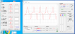
Ultimately, you will need to test the final chosen value(s) on the real track, with real (worst case) conditions (because the existing software operation isn't fully characterised), but we should be able to do quite a lot with the 'scope. Note that when you use the slow trace to display the train passing, then the "ripple" from the floodlights will cause the line to become wider (technically we call that an "envelope"). There's little sign of it in your screenshot in #105, which suggests that you can safely reduce the capacitor value; Some "ripple" is apparent, but it's a lower frequency than 50 Hz, so not directly related to the lighting (and hopefully can be ignored). Finally, as I suggested before, try to "fill" the screen more with the waveform(s) :- the amplitude of the "pulse" shown in #105 is about 50 ADC units! Also, add CH2 and Cursor lines to "mark" levels where things appear to start or stop working correctly, i.e. corresponding to the ADC levels that the software is responding to. It's difficult to explain exactly what to mark, but typically it will be the peak or trough of a waveform, where things start to "go wrong" (or become right).
Cheers, Alan.
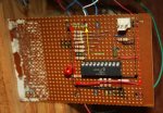
 a dodgy solder joint or something? And by "Earth" I think you mean the -ve common "bus" I've got on the board? (black wire).??


 I see what you mean about the shipping. It's more than double for two, but only by 50p. .....................................