Light Dependent Resistor (LDR) and LED lighting
- Thread starter Garahbara
- Start date
Hi,
Yes, like Lance, I usually get just the F-F dupont cables (note that various lengths are available), but I always have a reel of "Bare Tinned Copper" wire and a few pin-headers to hand. IMHO they can be a little stiff and the core very thin, so they do fail occasionally; but equally I've often got caught out by the ready-made croc. clip jumper cables, in assuming that one end is actually connected electrically to the other end.
As you've just raised the issue, a conventional (model-makers') "Servo" receives variable-width control pulses from the PICaxe, but is also connected separately to a d.c. power source (typically 0 and 5 volts). So a relay wouldn't be appropriate (or necessary). I would expect a Servo (for each "gate") to be fine, or a (geared) stepper motor might be worth considering. Otherwise you have the complication of a reversible dc motor, gearbox, limit switches, lots of connections and program code to worry about.
Now, here is my "review" of those 50 watt floodlights. But first I must emphasise that mine was very cheap, particularly being locally-sourced, so it might be a "fake" copy of a "cheap" Chinese product (or worse) and / or have been repaired (the mains lead soldering is particularly shoddy). First, I had examined quite a few ebay listings and there are subtle differences (although they do all claim 50 watts). One actually claimed 48,000 hours "lifetime" and another that it uses SMD2835 LEDs. Most manufacturers appear to rate these LEDs at 0.25 watt, but I did find one as 0.5 watt, therefore one watt per LED might be a rather "optimistic". The mains lead is ridiculously short (<10 cms) but well covered with sealant where it enters the case. The front cover / lens also has an apparently good quality (silicon rubber?) "O"-ring in a groove, so it might actually achieve IP66, even after re-assembly, which as I said before is just a matter of 12 Posidrive screws.
The circuit board is indeed aluminium-backed, which touches the back-plate, but there was no "heat-sink compound" between them. The backplate gets too hot to touch, so I hate to guess the temperature of the LEDs and other components. The front of the PCB is almost entirely copper-clad, with just narrow channels to isolate the "tracks", presumably to act as further heat-sinking. The copper is then coated with an insulator, so it's not easy to follow the tracks, but it can be seen that there are groups of 4 LEDs at the corners of copper squares. Thus there are 25 pairs of LEDs (each in parallel) connected in series. The diodes are rated at between 2.7 and 3.5 volts forward drop, so the chain needs about 80 - 90 volts, noting that this is a "230 volt ac" floodlight where the peak ac will reach about 350 volts.
The paired diodes will give a degree of "redundancy", i.e. if one fails "open circuit", then the chain can keep working through the other; its current will be doubled, so I'm not confident about it having a good lifetime, even if it does now have a better "share" of the heatsink. The first diode failing to a "short-circuit" will probably have a better outcome, its paired LED will go out but the current will be much the same, so just a fall of around 4% in the light output. Incidentally, if you look carefully at the top-right LED in the photo that I posted in #21, it appears to have a silver strip along its left edge. That is part of the PCB pads because its either "broken" or was a smaller size. I don't know if it ever worked, but it's unlit now, although (at the moment) its partner is still working. Particularly if you have a lot of these floodlights, I think it would be worth having (say) a weekly inspection to see if any LEDs (or pairs) are "out". Easy to see from a moderate distance, perhaps with the help of a pair of sunglasses.
With the front panel / lens removed, most of the components were fairly easy to identify, because they were all marked (rather faintly to my eyes). The "tube" at mid-right is indeed a MELF resistor, marked with violet-green-gold-gold bands, does measure 7.5 ohms and the "blue blob" is a Varistor marked CVR 471K which is rated at about 400 volts, as expected (its said to have a capacitance of around 70 pF). The diode bridge is marked MB10F which is rated at 1000 volts 0.8 amp and the SMD resistor above marked 105 (1 Mohm), perhaps just to discharge any stray capacitance? The SMD chips on the left-hand side are the only unknown, their full number is CD1000AE which Google doesn't recognise, even in "any foreign language". Note that the PCB is laid out with five sets of pads, but only three chips are fitted. The connections were quite easy to identify: the incoming (negative) power goes to Leg1 (of all three chips) and to one end of each 6.2 ohm resistor just below. The other end of each resistor goes to Legs 2, 3 and 4 of its associated chip and Legs 5 - 8 are connected to the lower end of the LED string. So obviously the LEDs' current must flow into Legs 5 - 8 of all 3 chips, out of Legs 2 - 4 and through the resistors, with Leg 1 effectively monitoring the current flow, by virtue of the voltage drop across the resistor(s).
If we consider the + supply voltage rising from zero, then initially no current can flow until it reaches about 25 x 2.5 = 62.5 volts when the LEDs start to conduct, with the current rising rapidly until about 90 volts when "something has to happen". Basically, the little SMD chips need to switch off, either partially or completely: the concept of "foldback current limiting" is well-known (e.g. in dc power supplies), i.e. as the voltage across the series transistor increases, the current is reduced to keep the power dissipation in the series element to a "manageable" level. But here, the foldback would appear to need to be enormous, because the peak voltage drop across the series element is at least 200 volts, compared with perhaps 4 volts across each LED, i.e. 50 times more dissipation (as their currents must be similar)!
If there were an inductor in the circuit, then the excess voltage (energy) could be stored in its magnetic field (when the transistor is On) and then released when the transistor switches Off (i.e. a Classic Switched-Mode or Class-D power supply). I have to assume that these little chips do that with the "stray" inductance of the mains cabling (unlikely to be approved of by the Electricity Supply or Wireless Telecom Authorities). Fortunately, I have a commercial mains isolation Transformer, so can measure the input power waveforms reasonably safely, but the little DPScope can't handle asynchronous switched mode at Radio Frequencies (however, there does appear to be some "switching" during the peak period). There also appears to be a lot of "RF noise" on my mains supply, for which I haven't yet managed to locate the source.
However, I was able to record the light output, using both a LDR and a Photo-Diode (which has a much shorter time-constant). I also monitored the "real" input power level, using a commercial (Maplin) power meter. Measuring input power used to be quite difficult (needing a dual-coil meter) even with sinusoidal signals (which these certainly aren't), because of the phase shift between V and I (i.e. the "Power Factor") of any non-resistive elements. I can't be sure of the accuracy of my meter, but it's quite easy now for a microcontroller (maybe even a PICaxe) to measure the instantaneous current and voltage, several times each ms, calculate each product (instantaneous power) and accumulate an average (i.e. rms) power level. My first observation is that when the floodlight was switched on, the input power was 40 watts, i.e. a little below specification, but then fell to just under 20 watts after heating up or a few minutes. So it appears that you may not have any problems with them being brighter than the original incandescent lights (and you'll save even more money for electricity).
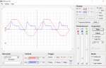
Here are two displays from the DPScope: the first compares the (photodiode) light detected (blue trace) with the mains voltage (red); I'm reasonably confident that the light output correlates quite well with the input current. It can be seen that the current (light output) increases rapidly about 3 ms after zero-crossing and falls back after about 4 ms, but the residual current seems excessively high, unless it's operating in a switching mode. I had expected the "unknown" chips might switch off (almost) completely during the "peak" region and then perhaps switch back on again when a "safe" level were reached on the falling side (giving a 200 Hz flicker). However, if the chips did switch off, then there would be little voltage across the LED string (unless a capacitor were also present), so the chips couldn't "know" when the voltage had returned to the safe threshold.
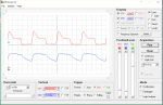
Finally, the second screenshot shows that the LDR (blue) has a significantly longer time constant that suppresses the initial "spike", but it still falls away quite rapidly, showing the time constant of the LDR is not particularly long. I did use a somewhat lower resistor than 100k (because I wanted to avoid saturation by the ambient light) but it didn't appear to greatly affect the time constant of the particular LDR that I was using. Therefore, it does look as if the PCBScope will be useful to measure the characteristics of your own set of floodlights, LDRs and complete system.
Cheers, Alan.
Yes, like Lance, I usually get just the F-F dupont cables (note that various lengths are available), but I always have a reel of "Bare Tinned Copper" wire and a few pin-headers to hand. IMHO they can be a little stiff and the core very thin, so they do fail occasionally; but equally I've often got caught out by the ready-made croc. clip jumper cables, in assuming that one end is actually connected electrically to the other end.
As you've just raised the issue, a conventional (model-makers') "Servo" receives variable-width control pulses from the PICaxe, but is also connected separately to a d.c. power source (typically 0 and 5 volts). So a relay wouldn't be appropriate (or necessary). I would expect a Servo (for each "gate") to be fine, or a (geared) stepper motor might be worth considering. Otherwise you have the complication of a reversible dc motor, gearbox, limit switches, lots of connections and program code to worry about.
Now, here is my "review" of those 50 watt floodlights. But first I must emphasise that mine was very cheap, particularly being locally-sourced, so it might be a "fake" copy of a "cheap" Chinese product (or worse) and / or have been repaired (the mains lead soldering is particularly shoddy). First, I had examined quite a few ebay listings and there are subtle differences (although they do all claim 50 watts). One actually claimed 48,000 hours "lifetime" and another that it uses SMD2835 LEDs. Most manufacturers appear to rate these LEDs at 0.25 watt, but I did find one as 0.5 watt, therefore one watt per LED might be a rather "optimistic". The mains lead is ridiculously short (<10 cms) but well covered with sealant where it enters the case. The front cover / lens also has an apparently good quality (silicon rubber?) "O"-ring in a groove, so it might actually achieve IP66, even after re-assembly, which as I said before is just a matter of 12 Posidrive screws.
The circuit board is indeed aluminium-backed, which touches the back-plate, but there was no "heat-sink compound" between them. The backplate gets too hot to touch, so I hate to guess the temperature of the LEDs and other components. The front of the PCB is almost entirely copper-clad, with just narrow channels to isolate the "tracks", presumably to act as further heat-sinking. The copper is then coated with an insulator, so it's not easy to follow the tracks, but it can be seen that there are groups of 4 LEDs at the corners of copper squares. Thus there are 25 pairs of LEDs (each in parallel) connected in series. The diodes are rated at between 2.7 and 3.5 volts forward drop, so the chain needs about 80 - 90 volts, noting that this is a "230 volt ac" floodlight where the peak ac will reach about 350 volts.
The paired diodes will give a degree of "redundancy", i.e. if one fails "open circuit", then the chain can keep working through the other; its current will be doubled, so I'm not confident about it having a good lifetime, even if it does now have a better "share" of the heatsink. The first diode failing to a "short-circuit" will probably have a better outcome, its paired LED will go out but the current will be much the same, so just a fall of around 4% in the light output. Incidentally, if you look carefully at the top-right LED in the photo that I posted in #21, it appears to have a silver strip along its left edge. That is part of the PCB pads because its either "broken" or was a smaller size. I don't know if it ever worked, but it's unlit now, although (at the moment) its partner is still working. Particularly if you have a lot of these floodlights, I think it would be worth having (say) a weekly inspection to see if any LEDs (or pairs) are "out". Easy to see from a moderate distance, perhaps with the help of a pair of sunglasses.
With the front panel / lens removed, most of the components were fairly easy to identify, because they were all marked (rather faintly to my eyes). The "tube" at mid-right is indeed a MELF resistor, marked with violet-green-gold-gold bands, does measure 7.5 ohms and the "blue blob" is a Varistor marked CVR 471K which is rated at about 400 volts, as expected (its said to have a capacitance of around 70 pF). The diode bridge is marked MB10F which is rated at 1000 volts 0.8 amp and the SMD resistor above marked 105 (1 Mohm), perhaps just to discharge any stray capacitance? The SMD chips on the left-hand side are the only unknown, their full number is CD1000AE which Google doesn't recognise, even in "any foreign language". Note that the PCB is laid out with five sets of pads, but only three chips are fitted. The connections were quite easy to identify: the incoming (negative) power goes to Leg1 (of all three chips) and to one end of each 6.2 ohm resistor just below. The other end of each resistor goes to Legs 2, 3 and 4 of its associated chip and Legs 5 - 8 are connected to the lower end of the LED string. So obviously the LEDs' current must flow into Legs 5 - 8 of all 3 chips, out of Legs 2 - 4 and through the resistors, with Leg 1 effectively monitoring the current flow, by virtue of the voltage drop across the resistor(s).
If we consider the + supply voltage rising from zero, then initially no current can flow until it reaches about 25 x 2.5 = 62.5 volts when the LEDs start to conduct, with the current rising rapidly until about 90 volts when "something has to happen". Basically, the little SMD chips need to switch off, either partially or completely: the concept of "foldback current limiting" is well-known (e.g. in dc power supplies), i.e. as the voltage across the series transistor increases, the current is reduced to keep the power dissipation in the series element to a "manageable" level. But here, the foldback would appear to need to be enormous, because the peak voltage drop across the series element is at least 200 volts, compared with perhaps 4 volts across each LED, i.e. 50 times more dissipation (as their currents must be similar)!
If there were an inductor in the circuit, then the excess voltage (energy) could be stored in its magnetic field (when the transistor is On) and then released when the transistor switches Off (i.e. a Classic Switched-Mode or Class-D power supply). I have to assume that these little chips do that with the "stray" inductance of the mains cabling (unlikely to be approved of by the Electricity Supply or Wireless Telecom Authorities). Fortunately, I have a commercial mains isolation Transformer, so can measure the input power waveforms reasonably safely, but the little DPScope can't handle asynchronous switched mode at Radio Frequencies (however, there does appear to be some "switching" during the peak period). There also appears to be a lot of "RF noise" on my mains supply, for which I haven't yet managed to locate the source.
However, I was able to record the light output, using both a LDR and a Photo-Diode (which has a much shorter time-constant). I also monitored the "real" input power level, using a commercial (Maplin) power meter. Measuring input power used to be quite difficult (needing a dual-coil meter) even with sinusoidal signals (which these certainly aren't), because of the phase shift between V and I (i.e. the "Power Factor") of any non-resistive elements. I can't be sure of the accuracy of my meter, but it's quite easy now for a microcontroller (maybe even a PICaxe) to measure the instantaneous current and voltage, several times each ms, calculate each product (instantaneous power) and accumulate an average (i.e. rms) power level. My first observation is that when the floodlight was switched on, the input power was 40 watts, i.e. a little below specification, but then fell to just under 20 watts after heating up or a few minutes. So it appears that you may not have any problems with them being brighter than the original incandescent lights (and you'll save even more money for electricity).
Here are two displays from the DPScope: the first compares the (photodiode) light detected (blue trace) with the mains voltage (red); I'm reasonably confident that the light output correlates quite well with the input current. It can be seen that the current (light output) increases rapidly about 3 ms after zero-crossing and falls back after about 4 ms, but the residual current seems excessively high, unless it's operating in a switching mode. I had expected the "unknown" chips might switch off (almost) completely during the "peak" region and then perhaps switch back on again when a "safe" level were reached on the falling side (giving a 200 Hz flicker). However, if the chips did switch off, then there would be little voltage across the LED string (unless a capacitor were also present), so the chips couldn't "know" when the voltage had returned to the safe threshold.
Finally, the second screenshot shows that the LDR (blue) has a significantly longer time constant that suppresses the initial "spike", but it still falls away quite rapidly, showing the time constant of the LDR is not particularly long. I did use a somewhat lower resistor than 100k (because I wanted to avoid saturation by the ambient light) but it didn't appear to greatly affect the time constant of the particular LDR that I was using. Therefore, it does look as if the PCBScope will be useful to measure the characteristics of your own set of floodlights, LDRs and complete system.
Cheers, Alan.
Hi Garahbara, I am not sure how you would use a relay with a servo or multiple servos. Remember that the Picaxe is sending a data signal to the servo, it is not the servo power supply. The data signal is a precise length pulse, with the length of the pulse proportional to the required servo position, and repeated ever 20 mS.. (All detailed is Section 2 under the servo and servopos commands, but see the interfacing circuit in section 3 for the wiring arrangement.) The manuals recommend that the servo power supply is separate from the Picaxe supply, servo power supply, with the zero volt rails connected together. I use two 780x regulators (X =5 for the Picaxe supply and 6 for the servo supply), fed from one plug pack for the two supplies and it seems to work quite well for standard RC servos. It might mot be separate enough if you were using really beefy robotics servos. If your boom gates are reasonably balanced, even the mini RC Servos should be adequate, I think.
If you are planning to send the data signal to two servos, it would be worth trying taking the two from one pin, each with the recommended resistor in the data line. However, I have not seen this approach documented and it would be worth trying it out on a breadboard on the beach first. Otherwise, there are TTL or CMOS hex buffer chips that you could supply the signal to several buffers in parallel to get precise separate outputs.
Eng460
Hi,
In programming terms, you normally send a "number" to the Servo and pre-define values such as : SYMBOL GATEDOWN = 123 : SYMBOL GATEUP = 189. Of course you could build "adjustments" into the gate mechanism, but normally you would adjust the Symbol(s) so that the value of GATEDOWN makes the bar exactly horizontal (and GATEUP as required). But the Servos (or the gate mechanisms) might not be exactly the same, so you would use separate Symbols and Program code for each gate.
The other issue is that you can't simply write a line of program that says : SERVOPOS gatepin , GATEUP because the servo will do that in a fraction of a second (the datasheet will specify a slew rate, e.g. 60 degrees / 100 ms.). Typically you will need a subroutine, or even an interrupt, to open / close the gates, for example:
For multiple gates with different sweep angles you'd need separate IF ... THEN sections for each gate within the LOOP.
Cheers, Alan.
Yes, it appears that you need a relay for that module as it says (in Red): "Do not connect any voltage to the SW terminals". It's a strange and rather inconvenient requirement because it's not generally satisfactory to drive a relay directly from a PICaxe pin (it needs a buffer transistor). The sound module might tolerate an opto-isolator or you may find a sufficiently sensitive reed relay, or a clarification of that specification / requirement.Also I will have to run the sound module off a relay. It is 9V - 14V DC. **here**
You may be misunderstanding how to use a Servo. The position of the Servo is determined by the exact width of a pulse measured in fractions of a millisecond, sent 50 times a second; a relay can't operate fast enough (nor probably be driven directly by the the PICaxe, as above). In principle, it's just a simple logic pulse which could be sent to multiple (probably all) the servos, but (particularly if you have enough pins on a 40X2) it would normally be easier to use one pin/pulse for each servo:.... drive multiple boom gates up and down. How many of those could I run off one set of pins? But a relay wouldn't hurt, would it?
In programming terms, you normally send a "number" to the Servo and pre-define values such as : SYMBOL GATEDOWN = 123 : SYMBOL GATEUP = 189. Of course you could build "adjustments" into the gate mechanism, but normally you would adjust the Symbol(s) so that the value of GATEDOWN makes the bar exactly horizontal (and GATEUP as required). But the Servos (or the gate mechanisms) might not be exactly the same, so you would use separate Symbols and Program code for each gate.
The other issue is that you can't simply write a line of program that says : SERVOPOS gatepin , GATEUP because the servo will do that in a fraction of a second (the datasheet will specify a slew rate, e.g. 60 degrees / 100 ms.). Typically you will need a subroutine, or even an interrupt, to open / close the gates, for example:
Code:
opengate{s}:
SYMBOL GATESPEED = 100        ; Milliseconds
DO
    gate1 = gate1 + 1        ; Increment gate upwards
    SERVOPOS gatepin1 , gate1
    PAUSE GATESPEED                 ; To determine the opening speed (or maybe Return from a timer interrupt)
LOOP UNTIL gate1 => GATEUP
RETURNCheers, Alan.
I've probably got the way these servo motors work wrong. I was wondering how you'd slow the things down. The specs say 0.1sec/60 degree. That's 0.3 secs for a full 180 degree rotation! EEEK. I'm looking for about 4 secs for a 90 degree rotation. And I thought you just reverse the polarity (or power the other pin) to rotate the other way. I do fully understand PWM, as the model locos use that to vary speed these days. If I can use PWM type code on the Picaxe servo motor pin, to control the motion speed then that will be great. I'll be able to work out the code to do that.Hi Garahbara, I am not sure how you would use a relay with a servo or multiple servos.
Eng460
I'm also going to use the "project board" **here** this time. Previously, I'd made my own from scratch using veroboard. See post #10. All 10 signals worth of them!
Thanks for the info. It's a learning process all the way.

Hi Garahbara,
I don’t believe that pwm is suitable for servo operation. (Edited to correct wording.)
Two options, Servo to initialise the pin and set first position, followed by Servopos to make adjustments to the position. Make the adjustments within a loop with pauses as suggested above.
Alternatively, pulseout, again in a loop, to send increasing length signals to progress the movement, and include in the loop a pause to space the signals to 20 mS. This method is more complex as you also need to generate that sequence of pulselengths. But quite doable when it is really necessary. For example when you have a timing issue due to a conflict with other commands which all use the same timer. I believe there is only one timer in each chip, but polling the ldr’s and executing simple logic commands may not involve those conflicts.
But to keep it simple, it is really much easier to use the servo and servopos commands. They will do what you want. Explore the alternative later when you have it working, and find a problem.
I can emphasise enough, read the command syntax and explanations in section 2, they really are what you need.
The thing that needs the experiment, is simply how many servos can you drive with identical motion from a single pin. Perhs try two then up to four to operate the four gates of a crossing, and see how it goes.
Eng460
Last edited:
Yep, thanks to you and Eng460 I now understand these servo motors a bit better. Seems I made the right choice of servo motor. I'll muck with them more to understand it a bit better when I get them, and setup the project board and start the programming. I also got a new programing cable (USB to stereo jack), rather than use my old handmake serial port to 3 pin plug cable (see veroboard post #10 top right).Hi,
Yes, it appears that you need a relay for that module as it says (in Red): "Do not connect any voltage to the SW terminals".
You may be misunderstanding how to use a Servo. T
Cheers, Alan.
With regards to the sound module, it's powered by applying/disconnecting power. There is no "control" of it. It will loop the sound bite in it, until power is removed. So I feel an appropriate 5V DC relay with applicalbe resistor if needed. (switching the 9 - 14 VDC separate sound module power supply)
Just an edit here......
I've checked the specs for the relay. It has a "coil resistance" of 50 ohms. Is this enough to connect it direct to the Picaxe I/O pin (on/off) without a resistor?
Last edited:
Again, Thanks for your response. It seem I've got the bits and pieces right, it's now just a matter of making it all work. It will be just two boom gates (servos). One on eachside of the 3 tracks.Hi Garahbara,
I don’t believe that pwm is not suitable for servo operation.
Two options, Servo to initialise the pin and set first position, followed by Servopos to make adjustments to the position. Make the adjustments within a loop with pauses as suggested above.
|
|
|
The thing that needs the experiment, is simply how many servos can you drive with identical motion from a single pin. Perhs try two then up to four to operate the four gates of a crossing, and see how it goes.
Eng460
But we're getting a little off track, so to speak.
 I need to solve the LED floodlight and LDR problem first.
WOW! You should write a book!Hi,
Yes, like Lance, I usually get just the F-F dupont cables (note that various lengths are available), but I always have a reel of "Bare Tinned Copper" wire and a few pin-headers to hand. IMHO they can be a little stiff and the core very thin, so they do fail occasionally; but equally I've often got caught out by the ready-made croc. clip jumper cables, in assuming that one end is actually connected electrically to the other end.
As you've just raised the issue, a conventional (model-makers') "Servo" receives variable-width control pulses from the PICaxe, but is also connected separately to a d.c. power source (typically 0 and 5 volts). So a relay wouldn't be appropriate (or necessary). I would expect a Servo (for each "gate") to be fine, or a (geared) stepper motor might be worth considering. Otherwise you have the complication of a reversible dc motor, gearbox, limit switches, lots of connections and program code to worry about.
Now, here is my "review" of those 50 watt floodlights.
|
|
|
Finally, the second screenshot shows that the LDR (blue) has a significantly longer time constant that suppresses the initial "spike", but it still falls away quite rapidly, showing the time constant of the LDR is not particularly long. I did use a somewhat lower resistor than 100k (because I wanted to avoid saturation by the ambient light) but it didn't appear to greatly affect the time constant of the particular LDR that I was using. Therefore, it does look as if the PCBScope will be useful to measure the characteristics of your own set of floodlights, LDRs and complete system.
Cheers, Alan.

Yep. I get your comments about the "dupont" cables. I got the "combo set" F-F, M- F & M-M.
Yep. I got the 5 VDC servo motors, so I can run them from the same power supply as the processor board. I now understand why the "connecting through a relay" was wrong. What everyone has said, also solves my puzzle of how to operate them at the motion speed I need. I now realise the servo motors are contantly powered, and it's commands (so to speak) that make them move. (I think I've now got this right??)
I have a spare LED Floodlight, so I"ll take it apart and post pics to see if it is the same.
I'll put the silly scope
together when it arrives sometime next week, and try and get some really good measurements off the signals' Picasxe boards. This time, I'll be able to clip the connectors on, rather than very very very awkwardly try and hold the multimeter probes on the board connections.Again, to all that have helped. Many thanks and your efforts are really appreciated.
TOOT!
Hi,
-----
A coil of 50 ohms across 5 volts requires 100 mA, but the PICaxe pins are rated as only 25 mA (and even that is not guaranteed to be delivered under all circumstances). You can't put a resistor (of sufficient size) in series with the relay coil, because then the relay won't work! So you definitely would need an amplifier (single transistor or FET) as shown in Manual 3 (for example). You might be able to find a 5 volt Reed Relay with a coil resistance of around 250 ohms, but a transistor is probably the easy option.
Cheers, Alan.
I think the Sound Module is intended to be permanently powered and the sound triggered (or looped) by linking the SW terminals (for a brief or long time depending on requirements) with a pushbutton / switch or Relay. But of course you should be able to switch the power rail directly with a relay (and maybe save a little continuous power drain). The only thing that would need to be checked is that the Loudspeaker doesn't "Click" or "Pop" when power (to the amplifier) is applied or removed.With regards to the sound module, it's powered by applying/disconnecting power. There is no "control" of it.
-----
I've checked the specs for the relay. It has a "coil resistance" of 50 ohms. Is this enough to connect it direct to the Picaxe I/O pin (on/off) without a resistor?
-----
A coil of 50 ohms across 5 volts requires 100 mA, but the PICaxe pins are rated as only 25 mA (and even that is not guaranteed to be delivered under all circumstances). You can't put a resistor (of sufficient size) in series with the relay coil, because then the relay won't work! So you definitely would need an amplifier (single transistor or FET) as shown in Manual 3 (for example). You might be able to find a 5 volt Reed Relay with a coil resistance of around 250 ohms, but a transistor is probably the easy option.
Cheers, Alan.
I have just noticed the typo in my comment about PWM above. The old double negative!
I meant to say that I don’t believe PWM will be suitable to drive a servo. You need to send those regular precise length pulses at about 20 mS intervals.
I will now go back and see if I can edit that post.
Apologies for the confusion.
Eng460
I meant to say that I don’t believe PWM will be suitable to drive a servo. You need to send those regular precise length pulses at about 20 mS intervals.
I will now go back and see if I can edit that post.
Apologies for the confusion.
Eng460
Thanks for that, Alan. I've looked at the crossing circuits and train detection boards that the sound module mob supply, and how to hook up the sound. Other makers of crossing control boards use the same sound module. These circuits power the sound module for the duration required and suggest a "jumper" across the SW pins. See pic. The sound module in question has a 7 second sound bite in it. Their detection modules use the same power source as the sound module. See **here** (bottom right).Hi,
I think the Sound Module is intended to be permanently powered and the sound triggered (or looped) by linking the SW terminals (for a brief or long time depending on requirements) with a pushbutton / switch or Relay. But of course you should be able to switch the power rail directly with a relay (and maybe save a little continuous power drain). The only thing that would need to be checked is that the Loudspeaker doesn't "Click" or "Pop" when power (to the amplifier) is applied or removed.
-----
A coil of 50 ohms across 5 volts requires 100 mA, but the PICaxe pins are rated as only 25 mA (and even that is not guaranteed to be delivered under all circumstances). You can't put a resistor (of sufficient size) in series with the relay coil, because then the relay won't work! So you definitely would need an amplifier (single transistor or FET) as shown in Manual 3 (for example). You might be able to find a 5 volt Reed Relay with a coil resistance of around 250 ohms, but a transistor is probably the easy option.
Cheers, Alan.
There is **this** relay at 47 ohms coil resistance. Probably not enough?
I could go with their train control/detection modules, but I want the challenge of making my own. I have no problems programming the Picaxe, as I have a strong computer programing background, and the signalling system is quite complex, however I think making my own sound module is a bit beyond my electronics capabilties at the moment, unless there is a kit form of something similar somewhere. I've looked and can't find one.
I'll probably start a new thread for the crossing system when I get one of them round tuit things. Priority at the mo is the LED floodlights and LDRs and getting that silly scope up and going.
lbenson
Senior Member
For the sound module, why not use a mosfet as a "low-side" switch instead of a relay as a "high side" switch? See manual 3 (though you wouldn't need the diode since you're not powering a motor). IRL520, IRL540, IRLZ44N are cheap options which can be driven directly from a picaxe pin. Your sound module would go where the (M) is in the manual 3 diagram.
I'm bookmarking all of these. I have no idea what some of it means, but I'm sure I'll work it out when I get that round tuit.For the sound module, why not use a mosfet as a "low-side" switch instead of a relay as a "high side" switch? See manual 3 (though you wouldn't need the diode since you're not powering a motor). IRL520, IRL540, IRLZ44N are cheap options which can be driven directly from a picaxe pin. Your sound module would go where the (M) is in the manual 3 diagram.
Hi,
The 5 volts coil voltage is a "Requirement" (give or take a volt) to make the relay work (operate), but its resistance is a "Characteristic" : you can measure the coil resistance with your multimeter and it should tell you that it's 47 ohms, but that very probably will not make it actually "work".
Personally, I instantly apply Ohms Law (as I've been doing for 50+ years) which tells me that the current will be 5 volts / 0.047 kohms = 106 mA. Note the use of "consistent" units, generally we want an answer in mA (Amps are too big), so we convert the resistance to kohms. Actually, it's this current which sets up the magnetic field that makes the relay operate, so this is the "fundamental requirement", and the relay coil could have been specified as (approximately) "100 mA through 50 ohms". But normally it's the supply voltage that has already been "decided" and the power-supply (designer) just has to provide whatever current is needed to perform the required function(s).
-------
Technically, we can consider your Sound Module as a "Two Terminal Network", i.e. a "Black Box" with two wires (terminals) coming out. There are many other examples such as a LED, Buzzer or a Motor (but not a Servo or Transistor which have 3 terminals). I know the audio PCB actually has six terminals, but we just connect a loudspeaker to the two SPKR terminals and link the two SW terminals and then at the "System Level", we draw a bigger box around the outside, through which we bring the PWR Positive and Negative wires/terminals.
The point about a two terminal network is that if we apply a suitable stimulus (e.g. connect a +12 volts "Potential Difference" between the + and - terminals) then it will do what it is defined to do. Therefore, we make a "circuit" (for electrical current to flow around) by connecting the + terminal to the positive side of a power supply (e.g. battery) AND the - terminal to the negative side of the power supply (often called ground or earth) to make it work. Then, you can break the circuit (i.e. stop the sound) by disconnecting EITHER the + or the - wire/terminal. This is the principle of the choice of either "High Side Switching" or "Low Side Switching" (or of course you can do both). If you are wiring up a house then the "Live" mains is dangerous, so you put the switches in the High side to make the loads "safe" when they are switched Off. Similarly, in a car it's convenient to connect most of the electrical components directly to the metal "chassis" (earth) and switch them on the High Side (positive) battery terminal.
However, for microcontrollers like PICaxe, it's very often more convenient to switch the "Low" side of simple Two-Terminal modules. A single transistor/FET can be driven "directly" from the PICaxe and then the High Side Terminal of the Load can go even to a different supply rail (than the PICaxe's), for example to +12 volts. For modest powers (like a relay and possibly the sound module) my "favourite" FET is the 2N7000, partly because it's cheap, small and I can easily remember its number.
Cheers, Alan.
PS: IMHO, the PICaxe 14M2 Audio Project Kit is an absolute steal, including the great little 14M2 on a PCB. It doesn't seem to be available from Wiltronics, but it appears to be only 4 UKP Airmail to Australia from Rev-Ed over here. Of course you would have to source your own MP3 sound file(s) and Micro SD memory card.
A matter of terminology, but to me it's "Too Much" (Load Current).There is **this** relay at 47 ohms coil resistance. Probably not enough?
The 5 volts coil voltage is a "Requirement" (give or take a volt) to make the relay work (operate), but its resistance is a "Characteristic" : you can measure the coil resistance with your multimeter and it should tell you that it's 47 ohms, but that very probably will not make it actually "work".
Personally, I instantly apply Ohms Law (as I've been doing for 50+ years) which tells me that the current will be 5 volts / 0.047 kohms = 106 mA. Note the use of "consistent" units, generally we want an answer in mA (Amps are too big), so we convert the resistance to kohms. Actually, it's this current which sets up the magnetic field that makes the relay operate, so this is the "fundamental requirement", and the relay coil could have been specified as (approximately) "100 mA through 50 ohms". But normally it's the supply voltage that has already been "decided" and the power-supply (designer) just has to provide whatever current is needed to perform the required function(s).
-------
Technically, we can consider your Sound Module as a "Two Terminal Network", i.e. a "Black Box" with two wires (terminals) coming out. There are many other examples such as a LED, Buzzer or a Motor (but not a Servo or Transistor which have 3 terminals). I know the audio PCB actually has six terminals, but we just connect a loudspeaker to the two SPKR terminals and link the two SW terminals and then at the "System Level", we draw a bigger box around the outside, through which we bring the PWR Positive and Negative wires/terminals.
The point about a two terminal network is that if we apply a suitable stimulus (e.g. connect a +12 volts "Potential Difference" between the + and - terminals) then it will do what it is defined to do. Therefore, we make a "circuit" (for electrical current to flow around) by connecting the + terminal to the positive side of a power supply (e.g. battery) AND the - terminal to the negative side of the power supply (often called ground or earth) to make it work. Then, you can break the circuit (i.e. stop the sound) by disconnecting EITHER the + or the - wire/terminal. This is the principle of the choice of either "High Side Switching" or "Low Side Switching" (or of course you can do both). If you are wiring up a house then the "Live" mains is dangerous, so you put the switches in the High side to make the loads "safe" when they are switched Off. Similarly, in a car it's convenient to connect most of the electrical components directly to the metal "chassis" (earth) and switch them on the High Side (positive) battery terminal.
However, for microcontrollers like PICaxe, it's very often more convenient to switch the "Low" side of simple Two-Terminal modules. A single transistor/FET can be driven "directly" from the PICaxe and then the High Side Terminal of the Load can go even to a different supply rail (than the PICaxe's), for example to +12 volts. For modest powers (like a relay and possibly the sound module) my "favourite" FET is the 2N7000, partly because it's cheap, small and I can easily remember its number.
Cheers, Alan.
PS: IMHO, the PICaxe 14M2 Audio Project Kit is an absolute steal, including the great little 14M2 on a PCB. It doesn't seem to be available from Wiltronics, but it appears to be only 4 UKP Airmail to Australia from Rev-Ed over here. Of course you would have to source your own MP3 sound file(s) and Micro SD memory card.
Last edited:
Alan,Hi,
PS: IMHO, the PICaxe 14M2 Audio Project Kit is an absolute steal, including the great little 14M2 on a PCB. It doesn't seem to be available from Wiltronics, but it appears to be only 4 UKP Airmail to Australia from Rev-Ed over here. Of course you would have to source your own MP3 sound file(s) and Micro SD memory card.
Not a bad little project module, even if I do say so myself!

I've had good look, and it will probably do what I want.
I found the full list of commands that the SPE035 player accepts **here** (page 19).
I've downloaded "Blockly" and it seems it has a basic set of SPE035 commands in the "output block", but they are limited.
They are very basic, though.
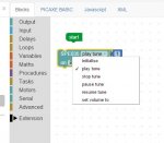
I'm sure with a bit of practice, I'll be able to code the serial output commands to control it the way I want it. I'm sure I can locate a relevant sound byte from the many sound effects sites around, or make my own from the local level crossing.
The AXE171 module has a couple of spare pins I think, so I'm sure I'll be able to drive it somehow from my main PICAXE-40X2 crossing control system. Or .......
 skip the AX171 module completely, and drive the SPE035 player directly from the 40X2!
After thought edit:
I could put this one in it ! https://www.videvo.net/sound-effect/train-crash-01/446885/
Last edited:
lbenson
Senior Member
Great collection of sounds, there. Didn't know such files were out there. Here's a search specifically for train whistles:

 www.videvo.net
Gotta get me one of them PICAXE-14 Audio Project Kits and play some sound effects.
Free Stock Video Footage Download 4K & HD Clips
Download free stock video footage with 4k and HD clips available. Click here to download royalty-free licensing videos from Videvo today.
www.videvo.net
Gotta get me one of them PICAXE-14 Audio Project Kits and play some sound effects.
Hi,
I have to confess that I added the Audio Project Kit to a previous (probably Black Friday) order and haven't actually built it yet! Certainly the additional 14M2 board is not essential, but it's such a great little chip, not much larger than the 08M2 (some people have even cut off its lower end to make a "10M2" ), but with all the extra RAM, EEPROM (slot), Table Memory and PWM pins, etc. of the larger M2 chips.
Perhaps I shouldn't say this, but all the .MP3 Sound Effects demo files from your original link appear to be downloadable. Also, it appears to be cheaper to order two separate Audio Project Kits, than to put them both in one order! That's due to Rev-Ed's steep shipping tariff, perhaps because of added costs of insurance or tracking data, etc.. BTW, in the UK we have an import tax-exempt threshold of 15 UKP; Memory cards are one of the things that I never buy from ebay (too easy to fake), but we have several reputable specialist sellers, based in the Channel Islands, who manage to price most items at 14.99 or less.
Cheers, Alan.
I have to confess that I added the Audio Project Kit to a previous (probably Black Friday) order and haven't actually built it yet! Certainly the additional 14M2 board is not essential, but it's such a great little chip, not much larger than the 08M2 (some people have even cut off its lower end to make a "10M2"
), but with all the extra RAM, EEPROM (slot), Table Memory and PWM pins, etc. of the larger M2 chips.Perhaps I shouldn't say this, but all the .MP3 Sound Effects demo files from your original link appear to be downloadable. Also, it appears to be cheaper to order two separate Audio Project Kits, than to put them both in one order! That's due to Rev-Ed's steep shipping tariff, perhaps because of added costs of insurance or tracking data, etc.. BTW, in the UK we have an import tax-exempt threshold of 15 UKP; Memory cards are one of the things that I never buy from ebay (too easy to fake), but we have several reputable specialist sellers, based in the Channel Islands, who manage to price most items at 14.99 or less.
Cheers, Alan.
Ibensen & Allycat,
Well I've order two of the PICAXE - 14 Audio Project kits. from Rev Ed. Two, in case the first one breaks! I see what you mean about the shipping. It's more than double for two, but only by 50p.
....... and forget that videvo sound effects link. They cost. However I've found **this** which includes the sound .wav editor. A pretty wizzy one too. List of free download sound effects is not that big, but I found exactly the one I want. It's 4 dings of Railroad Bell1 under "bells". Trimmed both ends, and put it on "loop" and just what I need. That's provided the SPEO35 player doesn't have any noticeable pause/delay in between "loops" of the "loop track" function.
Well I've order two of the PICAXE - 14 Audio Project kits. from Rev Ed. Two, in case the first one breaks!
I see what you mean about the shipping. It's more than double for two, but only by 50p........ and forget that videvo sound effects link. They cost.
However I've found **this** which includes the sound .wav editor. A pretty wizzy one too. List of free download sound effects is not that big, but I found exactly the one I want. It's 4 dings of Railroad Bell1 under "bells". Trimmed both ends, and put it on "loop" and just what I need. That's provided the SPEO35 player doesn't have any noticeable pause/delay in between "loops" of the "loop track" function.There may be a small delay, a few mS perhaps? For sounds that loop, I copy and paste them into a "long loop" of a few seconds worth of audio and then loop that "looped" soundtrack. That way any delay is only after one in every fifty sound effects and unless you listen for it, much less noticeable.
Thanks for the info. Looks good. I have created a "copy and paste" version as well, into a longer version. The thing is, if I create, say, a 15 sec "copy and paste" version, then to stop it,(turn "loop mode" off) it will play out the full 15 secs, or if I stop it instantly, I'll likely get "ding.. ding.. ding.. ding.. di.........." ie, chop of half way through a "ding". If I have a very short loop, say, (original effect is 1.07 secs, with 4 dings), then I can play "loop", then do "nomal" mode, and let it play out to the end of the 1.07 secs, and it will end with a full "ding" within a sec or so. Anyway, it's something like you suggest I can experiment with to get what I want, when I get the Audio Project kit set up.There may be a small delay, a few mS perhaps? For sounds that loop, I copy and paste them into a "long loop" of a few seconds worth of audio and then loop that "looped" soundtrack. That way any delay is only after one in every fifty sound effects and unless you listen for it, much less noticeable.
TOOT!
If your program can monitor the "busy" line from the SPE035 in a tight loop whilst it is playing, and if you have a small, fast uSD card, with a small file size for the playback file, the delay could be so near to zero that it is essentially zero. However, with large files, on a slow card and a lot of files on that card, that delay in starting playback can be quite a few seconds.
If playing a looped file, you could always monitor the playback and only issue a stop command at the point that the file is due to loop back?
If playing a looped file, you could always monitor the playback and only issue a stop command at the point that the file is due to loop back?
OK guys, I've re-read all this thread and taken your advice.
The silly scope, or periscope or whatever you want to call it, arrived today. I might even call it my Aussiescope.
Firstly, the software. There are TWO versions.
It took the laptop quite a while (a minute or two) to set up the USB HID Library for the device, after plugging it in.
http://dpscope.freevar.com/downloads_ii.html does not work with https://picaxe.com/hardware/add-on-modules/pcb-scope/ This software is PCscope II. It does not recognise the device. I don't know if it should recognise the device or not. Screen layout is a little different to.
https://picaxe.com/downloads/osc001.exe does work. This software is DP scope SE.
I soldered the pins onto the scope board, and mounted it onto a breadboard. The scope board is pretty "delicate", and needed some stabilty.
Next. The grabbers/clips to be used as probes. Two types were discussed. large and small. Pics are further up the thread. The mob I got the scope from were out of stock. They're on back-order. However, I wandered into the local furniture shop in town today, and they have a small electronics section. Voila. they had both types, so I got a few of each. Have soldered them onto the other end of male dupont wire and I've now got some probes. Both size grabbers and aligator clips as probes.
The male dupont pins are a bit "loose" in the breadboard, but I'll sort that with a section of double sided pin strips, I think. They are a bit thicker.
I've tested my Aussiescope with a AAA 1.5V battery and i get a signal on the screen.
Now to work out how to use it to do what I want to do, and that is measure properly that LDR voltage and see what those LED floodlights are doing
Again, guys, thanks so much for your help. It really is appreciated.
TOOT!
The silly scope, or periscope or whatever you want to call it, arrived today.
I might even call it my Aussiescope. Firstly, the software. There are TWO versions.
It took the laptop quite a while (a minute or two) to set up the USB HID Library for the device, after plugging it in.
http://dpscope.freevar.com/downloads_ii.html does not work with https://picaxe.com/hardware/add-on-modules/pcb-scope/ This software is PCscope II. It does not recognise the device. I don't know if it should recognise the device or not. Screen layout is a little different to.
https://picaxe.com/downloads/osc001.exe does work. This software is DP scope SE.
I soldered the pins onto the scope board, and mounted it onto a breadboard. The scope board is pretty "delicate", and needed some stabilty.
Next. The grabbers/clips to be used as probes. Two types were discussed. large and small. Pics are further up the thread. The mob I got the scope from were out of stock. They're on back-order. However, I wandered into the local furniture shop in town today, and they have a small electronics section. Voila. they had both types, so I got a few of each. Have soldered them onto the other end of male dupont wire and I've now got some probes. Both size grabbers and aligator clips as probes.
The male dupont pins are a bit "loose" in the breadboard, but I'll sort that with a section of double sided pin strips, I think. They are a bit thicker.
I've tested my Aussiescope with a AAA 1.5V battery and i get a signal on the screen.
Now to work out how to use it to do what I want to do, and that is measure properly that LDR voltage and see what those LED floodlights are doing
Again, guys, thanks so much for your help. It really is appreciated.
TOOT!
lbenson
Senior Member
Excellent progress and good reporting. I'm impressed that you have any local store with an electronics section, especially one which would sell such things as grabbers.
I never have my DPscope SE plugged into a breadboard--it's just dangling from its USB cable with flying leads running where I need them. I don't use it often, but I do like its portability, and the fact that it easily fits into a laptop bag.
I never have my DPscope SE plugged into a breadboard--it's just dangling from its USB cable with flying leads running where I need them. I don't use it often, but I do like its portability, and the fact that it easily fits into a laptop bag.
Hi,
Yes, the original DP Scope branched into two different products, "upmarket" to the DPScope II (which I also have) and "downmarket" to the DPScope-SE (Special Edition). The latter was then developed further to the PCB Scope, to reduce the cost further by removing the BNC connectors and the case (plastic box). So definitely the SE software is the (only) version to use.
Just a couple of further comments on using the DPScope. Because it uses only a single (USB) power supply (i.e. no negative rail), if you don't connect the probe input to anything, then the (measured) input level "floats" up to about 2.5 volts. Therefore to set the "ground" level / cursor you must actually connect the probe to the ground lead; with most 'scopes you can sometimes leave the input floating (although it may well pick up "mains hum"). Secondly, because it is powered by the PC it would be very wise to run a laptop only from its battery if connecting the (earth) probe to any other equipment.
Again to go slightly OT: I'm still in contact with some engineer colleagues who I worked with over 50 years ago and recently one of them posted a group photograph of that vintage. We actually managed to attach names to all the "faces", but the following discussion ensued:
" ..... He was in that dodgy (ahem) power lab where they had oscilloscopes un-earthed and connected to half mains! Far more risky than testing that new TTL stuff at 5 volts I did a couple of years later..... "
"In spite of the potential dangers we always stood the scopes on thick rubber mats and probed using one hand only with the loose ends of our ties pushed between the top two shirt buttons to avoid any rotating machines! "
Which raises two issues: The reference to "half mains" is that if you use any bridge rectifier (as does that floodlight) without a mains isolating transformer, whichever way you connect the Live/Neutral wires, then half of the time the "0 volts" (chassis/ground) line is connected to LIVE Mains. And the reference to neckties was not irrelevant; in the photo everybody is wearing a tie, including the "wireman" (now usually known as the technician) who was also wearing a white shirt (some of us were quite reactionary in wearing a striped or coloured shirt ! ).
Cheers, Alan.
Alan,Hi,
Just a couple of further comments on using the DPScope. Because it uses only a single (USB) power supply (i.e. no negative rail), if you don't connect the probe input to anything, then the (measured) input level "floats" up to about 2.5 volts. Therefore to set the "ground" level / cursor you must actually connect the probe to the ground lead; with most 'scopes you can sometimes leave the input floating (although it may well pick up "mains hum"). Secondly, because it is powered by the PC it would be very wise to run a laptop only from its battery if connecting the (earth) probe to any other equipment.
Cheers, Alan.
Thanks for the response. What you've said here means something. I've been right through the User Guide and have a reasonable handle on how the thing works. However, I've been stumped for the last hour or so, by the voltages showing on CH 1 & 2 without anything connected. Mean of 1.9V on CH1 (wobbles a bit), and 2.16V (steady) on CH 2. What you have said explains that. So I take it that this is expected, until I connect it to something using both probes. +ve & -ve (GND).
What you say about laptop and battery also makes sense, as the equipment under test could be connected to common (earth) by who knows where, what and why.
It's just gone midnight here, so I'll do those voltages on the LDRs tomorrow, and get back to you.
Thanks,
Alan.
TOOT!
lbenson
Senior Member
Can you explain what you mean here, and what risks you're concerned with. Personally, I would never try to use this scope on anything more than 12V, and would certainly not connect my laptop up with anything more than that. Perhaps when you say "(earth) probe" you mean something connected to real mains earth, not 0V on something running on 5V or 12V.because it is powered by the PC it would be very wise to run a laptop only from its battery if connecting the (earth) probe to any other equipment.
Hi,
One of the Cardinal Sins when making measurements with a "Real" Oscilloscope was to NOT connect the earth clip to a nearby point. That's because you nearly always want the waveform/measurement to be relative to the "local" Earth. With most of the Tektronix probes, you could even remove the normal "hook" tip and replace it with a "double-pins" adapter (signal and Earth) about 1 cm apart to make accurate high frequency measurements. And of course one of the "novice" mistakes with PICaxe projects is to "forget" to link the earth connections of separate power supplies, for example PICaxe and Servos or higher voltage/power modules.
But with the DPScope the bandwidth (and peak voltage input) is so much lower (and often its locality very close to the "Device Under Test") that an Earth connection may be completely unnecessary, so I'm probably being overly cautious. But I woudn't want to take the blame for destroying a $1000 Laptop, or perhaps even more valuable file contents. You may recall that hippy strongly disapproved of powering PICaxe projects from a USB port (which "should" be reasonably safe because the USB specification requires outputs be current-limited).
My main concern it that Earth and (mains) Neutral (or Earths of different devices) are often NOT the same voltage and their source impedances can be very low. It's quite common for power supplies to connect a capacitor between Earth and Neutral (e.g. to control Radio Frequency Interference), or many "Continental" products use "double-insulation" with no real Earth connection at all. The power adapter (charger) of my Samsung Netbook often makes quite a "splat" when I plug it in to the mains socket, indicating that a high voltage and/or current is flowing, if only for a brief time.
Cheers, Alan.
Mr Alleycat, Sir,
(and others, that may have something to offer)
I've done the and and and a fair bit of  and
and  . But I've got some readings for you.
They are as follows:
NOTES: Note the Ch1 Level. I moved it down to get a good detail of the readings. Ch2 is off.
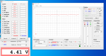
Something a bit puzzling. I thought as the light level dropped, the resistance of the LDR increased, and hence the "high" voltage reading should drop, the darker it gets. These samples seem to show the opposite. As the light levels go lower, the voltage reading increases. Note the complete blackout reading at 4.4V DC. So I hope I've done this right.
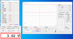
This is the ambient room light. No direct sunlight through windows, and quite low light levels with no room lighting and no train.
A stable ~3.63 V DC.
This is the LDR totally covered. Complete blackout.
A stable ~4.4V DC
Now for the good stuff.
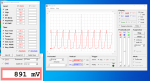
This one is LED Floodlights with LDR not covered. Note the "low/high" levels and the "rise/fall" time and particularly the "period". It appears the "off" (dark) cylce of the LED floodlights' strobe cycle is the peaks on the charts.
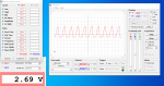
This one is LED Floodights with LDR covered by the train bogie. (LDR surrounded by wheels) ie. the "darkest point" of a passing train. Note the low/high voltage.
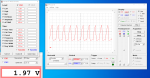
And the final one. LED floodlights with LDR covered by mid carraige.
So what do you think? There's definite strobing there. It's the "low" level reading which appears to be the level of "darkness" at the LDR. As it gets "darker" the "low" level reading rises. That's the puzzling bit to me.Thanks in advance for your thoughts.
Alan.
TOOT!
(and others, that may have something to offer)
I've done the
and and and a fair bit of and . But I've got some readings for you.They are as follows:
NOTES: Note the Ch1 Level. I moved it down to get a good detail of the readings. Ch2 is off.
Something a bit puzzling. I thought as the light level dropped, the resistance of the LDR increased, and hence the "high" voltage reading should drop, the darker it gets. These samples seem to show the opposite. As the light levels go lower, the voltage reading increases. Note the complete blackout reading at 4.4V DC. So I hope I've done this right.
This is the ambient room light. No direct sunlight through windows, and quite low light levels with no room lighting and no train.
A stable ~3.63 V DC.
This is the LDR totally covered. Complete blackout.
A stable ~4.4V DC
Now for the good stuff.
This one is LED Floodlights with LDR not covered. Note the "low/high" levels and the "rise/fall" time and particularly the "period". It appears the "off" (dark) cylce of the LED floodlights' strobe cycle is the peaks on the charts.
This one is LED Floodights with LDR covered by the train bogie. (LDR surrounded by wheels) ie. the "darkest point" of a passing train. Note the low/high voltage.
And the final one. LED floodlights with LDR covered by mid carraige.
So what do you think? There's definite strobing there. It's the "low" level reading which appears to be the level of "darkness" at the LDR. As it gets "darker" the "low" level reading rises. That's the puzzling bit to me.Thanks in advance for your thoughts.
Alan.
TOOT!
Hi,
** Yes, you are correct that when the light level falls the LDR resistance rises. But (IF**) the LDR is in the "high" side of the potential divider with the 100k resistor on the low side (which pulls the ADC input pin down towards earth). Thus, when the LDR resistance goes UP, the divider current goes DOWN (Ohms Law : I = V / R) and thus the voltage across the 100k goes DOWN towards earth (V = I * R).
It's possible to "invert" the divider (i.e. LDR to Earth, 100k to supply rail) and then the ADC input will rise when the light level falls, but for "Programming Clarity" it's sensible for the ADC value to increase when the light level rises. Personally, I very often do use the "inverted" mode ("Active Low") for switches and LDRs, etc., to make the hardware "simpler". With Active Low inputs, the "sensor" element (switch or LDR, etc.) can be connected directly to a (common) earth rail and the "Weak Pullup Resistors" (within the PICaxe) can be used in place of external resistors and a distributed supply rail.
Yes, those waveforms look much as I would expect. Just a couple of suggestions on "Oscilloscope Technique": I would normally use a faster timebase "sweep rate", probably 2ms/div or 1 ms/div to give only "a few" cycles across the screen (so that the curvature of the risetime is clearer). Also the "cursors" (lines) in the PCBScope control panel can be very useful (tick the box and drag the lines or "tabs" around the screen with the mouse). The "Earth" should be (automatically) shown by the little "underscore" on the left-hand side so it could be worth setting "marker lines" for the supply rail and/or the PICaxe software's "threshold" level. If using a digital input it would be about 1.5 volts (there are more specific details in the base PIC data sheet), or in your case using the ADC input you would typically set the cursor from the "ambient" waveform (depending exactly how your software determines that). Then move the cursor line (or introduce the second) to show half of that level, so you can see when the software will detect that "something has changed".
Another useful technique can be to set a very slow sweep speed, to show how the light level (and ripple) changes when something happens (e.g. a train going over). Related to this is the "single shot" mode and/or the "persist(ance)" option : Try them out to see when they can be "helpful" (and when not ).
Now you can try adding a few values of capacitor, probably directly across the 100k (capacitor negative lead to ground) but you can put it across the LDR as long as you ensure that the positive terminal always goes to the higher voltage (the supply rail in this case). I'd start with 10 uF and then try whatever values you have down to about 1 uF and up to 100 uF.
Cheers, Alan.
** EDIT: I've just re-read your post and the polarity does look "wrong". Unless you have the LDR to Earth and 100k resistor to the supply rail?
** Yes, you are correct that when the light level falls the LDR resistance rises. But (IF**) the LDR is in the "high" side of the potential divider with the 100k resistor on the low side (which pulls the ADC input pin down towards earth). Thus, when the LDR resistance goes UP, the divider current goes DOWN (Ohms Law : I = V / R) and thus the voltage across the 100k goes DOWN towards earth (V = I * R).
It's possible to "invert" the divider (i.e. LDR to Earth, 100k to supply rail) and then the ADC input will rise when the light level falls, but for "Programming Clarity" it's sensible for the ADC value to increase when the light level rises. Personally, I very often do use the "inverted" mode ("Active Low") for switches and LDRs, etc., to make the hardware "simpler". With Active Low inputs, the "sensor" element (switch or LDR, etc.) can be connected directly to a (common) earth rail and the "Weak Pullup Resistors" (within the PICaxe) can be used in place of external resistors and a distributed supply rail.
Yes, those waveforms look much as I would expect. Just a couple of suggestions on "Oscilloscope Technique": I would normally use a faster timebase "sweep rate", probably 2ms/div or 1 ms/div to give only "a few" cycles across the screen (so that the curvature of the risetime is clearer). Also the "cursors" (lines) in the PCBScope control panel can be very useful (tick the box and drag the lines or "tabs" around the screen with the mouse). The "Earth" should be (automatically) shown by the little "underscore" on the left-hand side so it could be worth setting "marker lines" for the supply rail and/or the PICaxe software's "threshold" level. If using a digital input it would be about 1.5 volts (there are more specific details in the base PIC data sheet), or in your case using the ADC input you would typically set the cursor from the "ambient" waveform (depending exactly how your software determines that). Then move the cursor line (or introduce the second) to show half of that level, so you can see when the software will detect that "something has changed".
Another useful technique can be to set a very slow sweep speed, to show how the light level (and ripple) changes when something happens (e.g. a train going over). Related to this is the "single shot" mode and/or the "persist(ance)" option : Try them out to see when they can be "helpful" (and when not
).Now you can try adding a few values of capacitor, probably directly across the 100k (capacitor negative lead to ground) but you can put it across the LDR as long as you ensure that the positive terminal always goes to the higher voltage (the supply rail in this case). I'd start with 10 uF and then try whatever values you have down to about 1 uF and up to 100 uF.
Cheers, Alan.
** EDIT: I've just re-read your post and the polarity does look "wrong". Unless you have the LDR to Earth and 100k resistor to the supply rail?
Last edited:
lbenson
Senior Member
For fun, if you wished, if you have an AC tranformer or wall plug (I keep one around), you can wire a resistor divider to bring the joint point down to the PICAXE supply voltage for the highest voltage and then monitor it as channel 2 to see exactly how it compares to your mains-synchronized LDR reading.
This sorta makes sense. I made these things a long time ago. When I really did have no idea what I was doing. And I think, if I recall correctly, I wired some of the earlier Picaxe signal boards up, so that the pin pulling resistor went to the +ve rail instead of the recommended -ve. So it pulled the Picaxe pin the opposite of the later modules I made. So I had to "reverse" all the code for the later signal boards I made properly. Test for "high" instead of "low", (and vice versa), or > instead of < etc for the later boards. The module I did the sillyscope with may be one of those earlier ones. Would that explain the results? ie opposite of what I expected, and as you've explained?Hi,
It's possible to "invert" the divider (i.e. LDR to Earth, 100k to supply rail) and then the ADC input will rise when the light level falls, but for "Programming Clarity" it's sensible for the ADC value to increase when the light level rises. Personally, I very often do use the "inverted" mode ("Active Low") for switches and LDRs, etc., to make the hardware "simpler". With Active Low inputs, the "sensor" element (switch or LDR, etc.) can be connected directly to a (common) earth rail and the "Weak Pullup Resistors" (within the PICaxe) can be used in place of external resistors and a distributed supply rail.
I note your comments on "Oscilliscope technique" and know what you mean there.
Next. Capacitors. I know of capacitors as having a "voltage" spec as well. Will any voltage spec do? Say 16V or 25V? Just so long as the spec isn't below 5 V? ie. Pick a voltage that is closet to, but not lower than the voltage I'm working with.
Electolytic? Ceramic? Does that matter as well?
**these capacitors**???
Will the capacitor still work properly on the "older" boards? ie. pin pulling to +ve?
I don't have any capacitors to hand, so I'd have to order them online. Other than some little yellow square things????
. With 100nj100 written microscopically across the top. Don't even know why or what I got them for. **these** Your thoughts again appreciated.
Alan.
TOOT!
I think I know what your saying here. For curiosity value, compate the LDR/Picaxe frequency/phase timings to the AC mains frequency/phase timings. See if the peaks and troughs match at the same points. Although if I read the oscilliscope reading correctly, the period and fequency reading (10.0 ms & 100.0 Hz) is double the mains AC frequency (50 Hz). I think it was Alleycat's analysis of the LED Floodlights (further up the thread) said the electronics in the LED Floodlights would produce strobing at double the mains frequency. (50 Hz * 2 = 100 Hz, as indicated on the oscilliscope) Something about a bridge rectifier, or transitor or something???For fun, if you wished, if you have an AC tranformer or wall plug (I keep one around), you can wire a resistor divider to bring the joint point down to the PICAXE supply voltage for the highest voltage and then monitor it as channel 2 to see exactly how it compares to your mains-synchronized LDR reading.
I do have access to a 17V AC outlet that powers the point/turnout motor solenoids of the train track and a 17 V AC 10 AMP power supply that powers the entire train system and locos, and DIgital Train Control systems. What sort of resistor would I need to put in the line to bring it down to 6V? But I think I might need to spend more time in electronics school first.
before mucking with that one, and risk blowing up either of those, or something else, accidentally!
Alan.
TOOT!
Aries
New Member
You're looking for a voltage divider. 17VAC is something like 25V peak, so you need to divide it down by a factor of at least 5. For safety, use a factor of about 10 to start with, so ..What sort of resistor would I need to put in the line to bring it down to 6V? But I think I might need to spend more time in electronics school first.
connect one end of the AC to Picaxe 0V. Then 10K from Picaxe 0V to the pin, and 100K from the pin to the other end of the AC. This should give you a ratio of 10/(10+100), i.e. 1/11 to start with.
Buzby
Senior Member
Hi,... But I think I might need to spend more time in electronics school first.
I'm with you 100% on that. Too risky if you are not confident about your skills in this area.
17V AC won't hurt you, but one wrong wire and it will kill your PCB scope, the USB port, and probably the laptop.
That 10mS waveform is proof enough that the LDR can see the 100Hz flicker from a full-wave rectified LED supply
TOOT TOOT !,
Buzby
Hi,
The specification of the capacitors is not too important, whatever you can get easily and cheaply (maybe that "local furniture store" again?). Basically, a few 10 uF at 16 - 25 volts, 47 or 100 uF at 16v electrolytics, and perhaps 1 uF ceramics (you normally won't find much larger). An advantage of the ceramics is you don't need to worry about polarity, put two in parallel and you have 2 uF , put two 10 uF electrolytics in series (with one reversed, so either + or - are joined) and you have 5 uF with no concern about polarity. Then two 10 uF in parallel for 20 uF (or 2 x 47 uF in series) and continue to 47/50 and/or 100 using the same principles. Don't bother with the "tantalum" type which are expensive and polarised. That should cover the range you need to test.
An auxiliary transformer may help to synchronise the 'scope to 50 (or 60) Hz, but might not indicate the important "phase (shift)" of the signal (i.e. the relative zero-crossing or peak voltage points), so I wouldn't bother. A transformer works by converting voltage to current, which generates a magnetic field, which then generates a voltage and current in the secondary winding, with potential phase shifts at all those stages, particularly under light (i.e. low) loading. But if you want to try, you only need to get the peak voltages down below the PCBScope's +/- 20 volts input limit. I'd try a 1 Mohm series resistor (or a R + R divider where R > 1k if you only have a few resistors) without connecting the "Earth" pin. If that produces "rubbish" then try linking the earth pins by perhaps 10k or 1k. If that doesn't work, listen to Buzby.
To make my measurements, I had a "professional" mains isolating transformer, so I could (safely) read the actual voltage applied to the floodlight. But that still wasn't easy as I had to make a voltage divider, because of the low maximum input voltage of the DPScope, and I was troubled by mains interference/noise. I don't know if my neighbour has one of the (horrible) "mains line" communication systems; I find a WiFi repeater is much more satisfactory.
Cheers, Alan.
Oh dear........
Did some more Aussiscope testing today. And I thought I'd look at the Picaxe supply bus voltage. I run a power bus from one signal/board to the next. Powered at the source of the bus. Woe and behold, it looked like this.
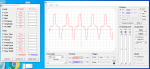
That don' t look like 5V DC to me, which I'm sure I've been running these things with for years. Looks like AC to me, with AC RMS of 4.16V.
So I go check the power pack, and it says 5V AC on it.
So I go check the Picaxe manual. It says.

Is it any wonder these things work at all? Does it matter???
TOOT!
PS: I tested the LDR on another board, and I got the response I expected. Low light levels = lower peak voltage.
Did some more Aussiscope testing today. And I thought I'd look at the Picaxe supply bus voltage. I run a power bus from one signal/board to the next. Powered at the source of the bus. Woe and behold, it looked like this.
That don' t look like 5V DC to me, which I'm sure I've been running these things with for years. Looks like AC to me, with AC RMS of 4.16V.
So I go check the power pack, and it says 5V AC on it.
So I go check the Picaxe manual. It says.
Is it any wonder these things work at all? Does it matter???
TOOT!
PS: I tested the LDR on another board, and I got the response I expected. Low light levels = lower peak voltage.
Hi,
That waveform looks very "suspicious" and my inclination is that "Earth" is not what you think it is, BUT.....
If the "Earth" (local to the point that Channel 1 is measuring) is "dirty", then connecting it to the PCBScope might cause damage, so: Connect the Channel 2 probe to the Earth (0 volts) point close to the Channel 1 probe, and "tick" CH2 . The (horizontal) blue line should be just that, of course; if it isn't then you've learnt something.
That's another feature that "big" scopes have; a "differential" mode, either a "dedicated" facility (or the early Tektronix 'scopes actually had an optional "plug in" Differential Pre-amplifier module), or simply an "invert signal" for one of the channels and an "Add" mode for the two channels (or of course a "Subtract channels" mode).
Cheers, Alan.
inglewoodpete
Senior Member
I concur with Alan about the earth connection.
Also you should look at the capacitance you have across the power rails on each board. Depending on the power requirements, you may need a few hundred microfarads on each board.
Also you should look at the capacitance you have across the power rails on each board. Depending on the power requirements, you may need a few hundred microfarads on each board.
Ok lads......
I checked out the local "furniture shop" this morning. To check on their supply of capacitors. It was sadly lacking. If it was resistors you're after, then thems is ya shop!
Only had ceramic capacitors in the big stack of little plastic drawers.
They only had 50V ceramic capacitors.
The hieroglyphics on the little packets say:
CAP CER NPO nnP 50V +/-
"nn" appears to be the uf value?? "nn" values are 10, 22, 47 & 100. They had others that were 220, 440 etc etc.
I got an assortment of each. 2 per packet, and 2 packets each.
Will these do what I want or should I condemn them to the recyle bin and go electrolytic?
Is there something I can do to test the theory? Rig up something on a breadboard, with Powersupply and LDR and capacitors under the LED floodlights, and test with the sillyscope?? The existing Picaxe boards and LDR connections are very awkward and difficult to access under the train layout to try and do some experilmentationals with.
Nextly, considering the concerns re the 5 V AC picaxe power supply I'm using, (although the things have worked fine for years), I also got a 5V DC 3 AMP powerpack to replace the 5V AC one. I know my power bus follows through properly from board to board. +ve & -ve (red and back wired bus). I have no idea how I picked which wire to which connection on the existing 5V AC supply.
Nextly. The parcel turned up today for the bits and pieces of the level crossing control. However the 28/40 pin Picaxe project board for it was "out of stock" and is on back order. So that little project is going to have to wait.
So, A yay or nay on those capacitors?
Thanks again for all your help.
Alan.
TOOT!
I checked out the local "furniture shop" this morning. To check on their supply of capacitors. It was sadly lacking. If it was resistors you're after, then thems is ya shop!
Only had ceramic capacitors in the big stack of little plastic drawers.
They only had 50V ceramic capacitors.
The hieroglyphics on the little packets say:
CAP CER NPO nnP 50V +/-
"nn" appears to be the uf value??
"nn" values are 10, 22, 47 & 100. They had others that were 220, 440 etc etc.I got an assortment of each. 2 per packet, and 2 packets each.
Will these do what I want or should I condemn them to the recyle bin and go electrolytic?
Is there something I can do to test the theory? Rig up something on a breadboard, with Powersupply and LDR and capacitors under the LED floodlights, and test with the sillyscope??
The existing Picaxe boards and LDR connections are very awkward and difficult to access under the train layout to try and do some experilmentationals with.Nextly, considering the concerns re the 5 V AC picaxe power supply I'm using, (although the things have worked fine for years), I also got a 5V DC 3 AMP powerpack to replace the 5V AC one. I know my power bus follows through properly from board to board. +ve & -ve (red and back wired bus). I have no idea how I picked which wire to which connection on the existing 5V AC supply.
Nextly. The parcel turned up today for the bits and pieces of the level crossing control. However the 28/40 pin Picaxe project board for it was "out of stock" and is on back order. So that little project is going to have to wait.
So, A yay or nay on those capacitors?
Thanks again for all your help.
Alan.
TOOT!